
Macrotel X1/X2 Multimode
Macrotel X1/X2 Multimode
Multimode Telephone Hybrid

Macrotel X1 Multimode and Macrotel X2 Multimode can manage one or two POTS (Plain Old Telephone Service) landline, VoIP, BT or GSM (with optional interface) telephone connections.
Audio enhancement features are custom designed to guarantee the best quality in phone calls, the internal framework based on DSP (Digital Signal Processor) works in real time taking care of the telephone signal process delivering the best possible audio performance. Macrotel X1/X2 Multimode it’s a Telephone Audio Processor able to shape the sound to optimize the yield of every single phone call.


Macrotel X1/X2 Multimode manages calls from POTS (Plain Old Telephone Service), VoIP, BT or GSM (optional) telephone connections and it embeds a web server and a simple and intuitive GUI accessible from any device and browser. For services synchronisation and logs Macrotel X1/X2 Multimode connects to a NTP server.
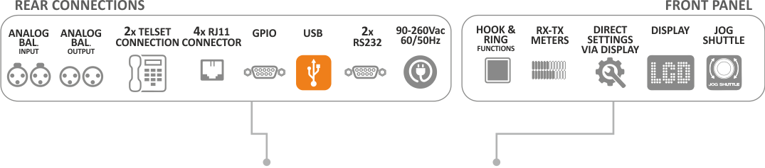
The main XLR input and output connectors can manage analogue or AES/EBU signals according to the device settings (AES/EBU input/output is optional) while a second XLR analogue output is also available. When in BT mode the two outputs act like a stereo balanced output.
Macrotel X1/X2 Multimode records telephone calls on a USB flash memory plugged in the USB front panel slot. Audio will be recorded in PCM format with a self-explaining filename based on date/time and can include the RX audio only or both RX and TX signals. It is also possible to send an RTP-PCM audio stream to an external PC to record the call, in this case the recording will include the RX audio only or both RX and TX signals.
Customers using any digital console of the Oxygen series can control Macrotel X1/X2 Multimode through the network, just adding its IP address. In this way there is no need to use a GPIO but you should only connect the Macrotel X1/X2 Multimode to the Oxygen Console through the Telco module.
A multiple GPIO port allows to manage the device from external equipment, like audio console or PC. System sends “Ring”, “Hold”, “Hook” and “REC” status and manages “Hook”, “Rec”, “Mode” and “Hold” functions. On the front panel an audio meters with 18 LEDs shows the RX and TX audio level of each channel. Additional LEDs show working Mode and Power on. Power supply can be used between 90 and 260 V AC – 47-63 Hz: this allows to use it worldwide.
- Multi-line digital telephone hybrid POTS/GSM/VOIP
- Automatic gain control (AGC);
- Digital echo canceller;
- Hold caller/attenuator;
- Expander and compressor;
- Audio limiter;
- Digital AGC processor with 3 bands fully parametric EQ;
- Analog and AES/EBU digital inputs and outputs (optional);
- 1 line and 2 lines models;
- POTS/PSTN;
- GSM Quad Band (optional);
- Integrated web server for remote control;
- Separate send and receive;
- LAN and USB ports;
- Auto-answer and disconnection;
- Balanced XLR I/O;
- Remote control software and dialer;
- Echo cancellation through a digital process on DSP (POTS);
- Advanced audio processing functions: AGC, parametric EQ, audio filters, compressor, expander and limiter;
- Internal Web Server allows device configuration;
- Automatic setup;
- 1 selectable XLR input: Analogue or AES/EBU (AES/EBU is optional);
- 1 selectable XLR output: Analogue or AES/EBU (AES/EBU is optional);
- 1 balanced XLR analogue output;
- Phone call recording in PCM format on USB support (RX only or RX+TX);
- Front panel led meters displaying RX/TX levels;
- Audio stream generation in RTP/PCM format (RX only or RX+TX);
- Front panel LED: Gain RX, Gain TX, Mode;
- “Hook” and “Hold line” lighted buttons;
- 4 GPI interfaces, 4 GPO interfaces;
- Integrated Caller Identifier (CID) – only for VOIP;
- Input and output call logs;
- G711-G722 VOIP audio codecs:
- Local telephone output (POTS).
GENERAL FUNCTIONS
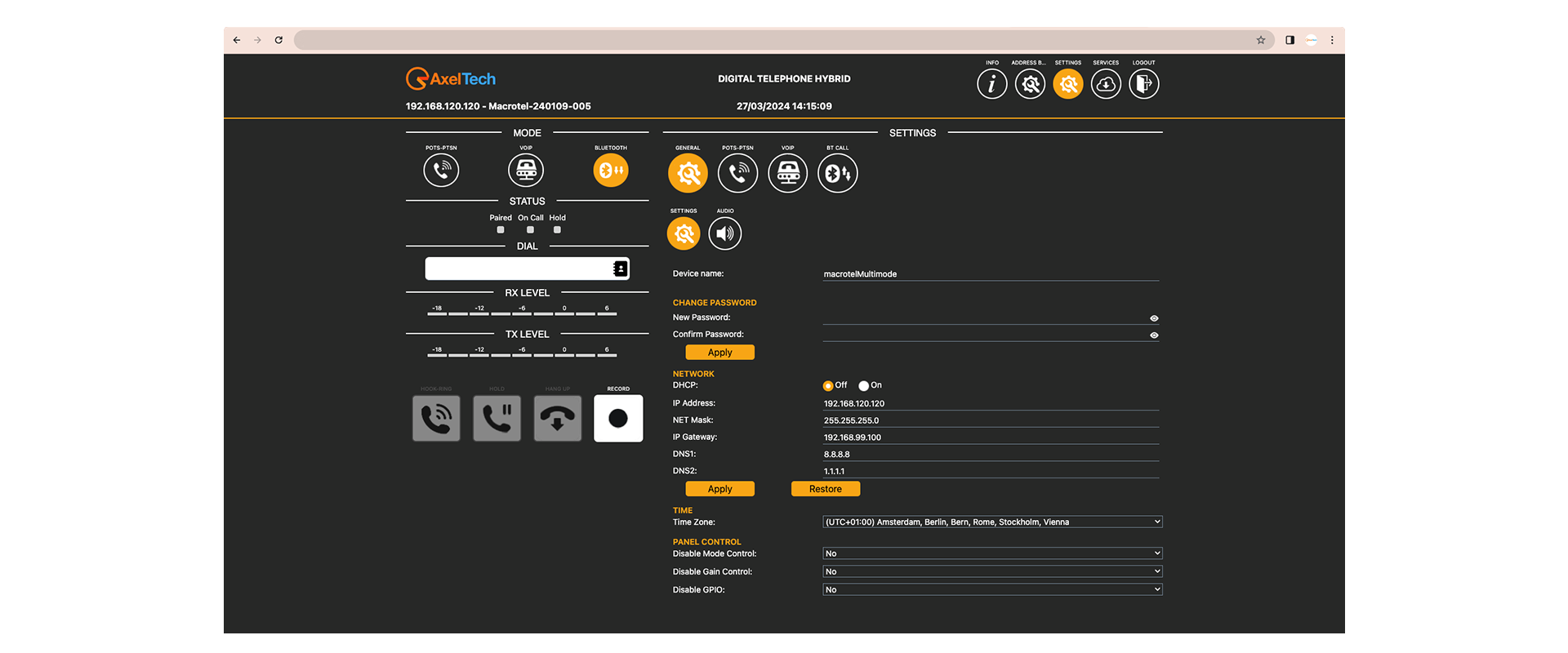
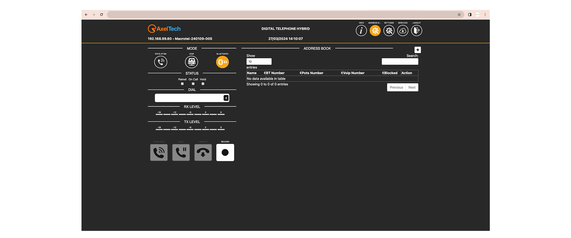
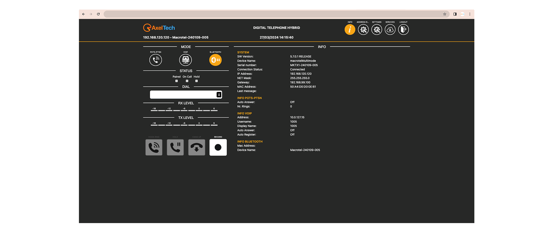
Macrotel X1/X2 Multimode parameters can be configured through a web interface and its web user friendly GUI is available from any kind of device: PC, notebook, tablet, smartphone.
Macrotel X1/X2 Multimode supports TCP/IP standards such as HTTP for web GUI and UDP for streaming. Connection to external NTP server (Internal RTC with buffer) for time synch and ethernet/GPIO connection are available. Macrotel X1/X2 Multimode has stainless steel enclosure and a front panel with 22 levels and status LEDs. Power supply: 90-260V AC 47-63 Hz – 10 W (green approach).
POTS MODULE
Macrotel X1/X2 Multimode embeds standard RJ11 sockets for connecting to the telephone line and to an external telephone set. Internal DIAL system via DTMF for direct call is also available (so the external telephone set is not mandatory). It is possible to export logs phone numbers of incoming and outgoing calls and save them on a USB key (date, call time start, call time end). It is possible to set the automatic telephone line hooking after a settable number of rings and automatic telephone line release based on the “dropped line” tone (this feature can be disabled). Among the many customizable parameters Macrotel X1/X2 Multimode also has adjustable AGC, compressor/limiter and equalizer parameters and adjustable telephone band (with low or hi-cut).
BT MODULE
Macrotel X1/X2 Multimode has a fully certified BT version 3.0 audio module, compatible with BT version 2.1+EDR, 1.2 and 1.1. SIP version 2.0 (RFC 3261) is also on, together with adjustable AGC, compressor/limiter and equalizer parameters.
Embedded BT stack profiles: A2DP and HFP/HSP. Supports iAP profile discovery for iPhone® and iPod® BT accessories G.711u. Dual-channels differential audio input and output for highest quality audio. Certifications: FCC, IC, CE.
VoIP MODULE
The VoIP is available through a standard network RJ45 connector. Macrotel X1/X2 Multimode embeds SIP version 2.0 (RFC 3261). Authentication methods: SIP/IAX Dynamic Registration (Register) and SIP Static IP authentication. Supported audio codecs: G.711u (PCM u) | G.711a (PCM a) | G.722 | G.722.1 24/32. Automatic telephone line hooking (after a settable number of rings) and automatic telephone line release based on the “dropped line” tone (this feature can be disabled). Logs of phone numbers of incoming and outgoing calls (date, call time start, call time end) are available and can get exported, as all the other logs, on USB key. Adjustable AGC, compressor/limiter and equalizer parameters are on as well as for the others connections mode.
Please note that supported PBXs and phone service providers require interoperability with established VoIP providers. Such services are delivered via either a SIP-based IP PBX or through a cloud-based telephone service provider. These are complex services, therefore sometimes configuring AxelTech products to interact with them can be difficult or not possible.
AxelTech constantly updates its products to reach compatibility with these services, nevertheless incompatibilities are still possible and any change or update made by the service providers or by the PBXs themselves can cause problems with Macrotel X1/X2 Multimode in VoIP mode.
Here below you can find the list of the PBXs and VoIP service providers that have been used successfully by our customers with our products: these services are not fully compatible 100% of the time, as one update can interfere with the compatibility and of course we cannot guarantee to test them. We would suggest to customers who are considering using Macrotel X1/X2 Multimode with services other than those listed below, to contact our technical support team before purchasing this service.
We will allow the customer to return the AxelTech product and obtain a refund if the device is not compatible with the service he has selected. The following services are currently reported as compatible with AxelTech Products: Supported PBXs: Asterix Supported VoIP Providers: Olimon Tel.
DIGITAL
- Digital audio AES/EBU input/Output
| GENERAL | |
|---|---|
| Power supply: | 90-260 V AC / 47-63 Hz |
| Power consumption: | 10 W |
| Dimensions WxHxD: | 483 x 44,5 x 140 mm (1 rack unit 19”) |
| Weight: | < 2Kg |
| ANALOG AUDIO INPUT | |
|---|---|
| Connectors: | Balanced on XLR – EMI Suppression |
| Input impedance: | 50 KΩ |
| Adjustable via software: -9 dBu ÷ +15,0 dBu | |
| Level range: | –20,0 dBu ÷ + 20,0 dBu |
| Input level max.: | +20,0 dBu |
| CMRR input: | >60 dB (20 Hz ÷ 20 kHz) |
| DIGITAL AUDIO INPUT (OPTIONAL) | |
|---|---|
| Connectors: | Balanced on XLR – EMI Suppression |
| Input impedance: | 110 Ω |
| Format: | AES3/EBU & SPDIF |
| Sample rate: | 32, 44.1, 48, 64, 88.2, 96 KHz |
| Nominal Input Level (sensitivity): | From 0,0 dBFs to –24dBFs (0,1dB step) |
| Level range: | 0,0 dBFs ÷ -36dBFs |
| ANALOG AUDIO OUTPUT | |
|---|---|
| Connectors: | Balanced on XLR – EMI Suppression |
| Output impedance: | 47 Ω |
| Output level: | Adjustable via software: -9dBu ÷ +15,0 dBu |
| Level range: | –20,0dBu ÷ + 20,0dBu |
| Output level max.: | + 20,0dBu |
| CMRR output: | >60dB (20Hz ÷ 20kHz) |
| DIGITAL AUDIO OUTPUT (OPTIONAL) | |
|---|---|
| Connectors: | Balanced on XLR – EMI Suppression |
| Input impedance: | 110 Ω |
| Format: | AES3/EBU |
| Sample rate: | 32, 44.1, 48, 64, 88.2, 96 KHz |
| Nominal Input Level (sensitivity): | From 0,0 dBFs to –24dBFs |
| Level range: | 0,0 dBFs ÷ -36dBFs |
| POTS INTERFACE | |
|---|---|
| Connectors: | 2x RJ11 Line and Telephone set |
| Output impedance: | Selectable |
| Bandwidth telephone line | 170Hz - 4.6kHz |
| Echo canceller suppression: | > 40dB |
| Signal to Noise Ratio (S/N) | ≤ -60dBu (Ref.0dB @1KHz Analog Out) |
| Frequency Response | ± 3dB (TBR21) ± 2dB (600 Ω) |
| Audio distortion | ≤ 0.2% (Ref.0dB @1KHz Analog Out) |
| VOIP INTERFACE | |
|---|---|
| Protocol: | SIP Version 2.0 - RFC 3261 |
| Codec Audio Compatibility: | G.711u (PCM u), G.711a (PCM a), G.722, G.722.1 24/32 |
| Authentication Methods: | SIP/IAX Dynamic Registration (Register) SIP Static IP authentication |
| BT INTERFACE | |
|---|---|
| Compatibility: | Fully certified BT version 3.0 audio module, Fully compatible with BT version 2.1+EDR Compatible with 1.2 and 1.1 |
| Connection mode: | Embedded BT stack profiles: A2DP and HFP/HSP |
| IOS: | Supports iAP profile discovery for iPhone® and iPod® BT accessories G.711u (PCM u) |
| GENERAL | |
|---|---|
| GPIO Inputs/Outputs: | 4 GPI 4 GPO |
| Communication Port: | 1xLAN |
| Front Panel LEDs: | 18+4+2 |
| USB: | Type A |
| Operating Temperature: | 0°C ÷ 50°C |
| COMMUNICATION | |
|---|---|
| Configuration Software: | Web Server |
| Password Protection: | Yes |
| UDP, TCP, HTTP, SNTP. | Yes |
| Supported Network Protocols: | HTTP, UDP, TCP, NTP, |


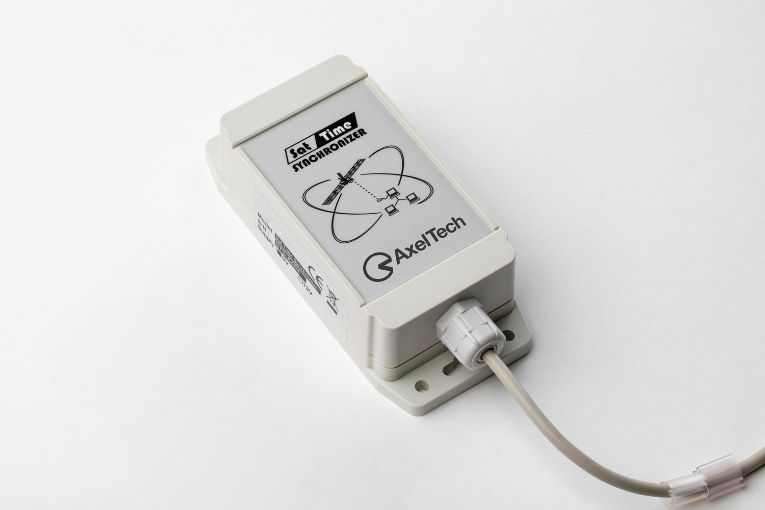
Sat Time Synchronizer
Radio
On Time, In Time
Useful in everything
SAT TIME SYNCHRONIZER is the cost effective solution to automatically synchronize the PC clock with exact and absolute time broadcast by GPS satellites (GMT – Greenwich Mean Time). SAT TIME SYNCHRONIZER is very useful in all those applications where it is necessary to have the precise and reliable current time (f.i. Time Code generation, A/V recording monitoring and certification for law obligations and data logging, time signalling in TV and radio stations, etc.).
The software and hardware installation is fast and easy and even not skilled technicians can operate it correctly. Normally you just need to place the receiver next to a window and connect it to a Pc through a serial cable. SAT TIME SYNCHRONIZER doesn’t need external power supply: it is powered directly by the PC power supply through a special adapter (supplied).
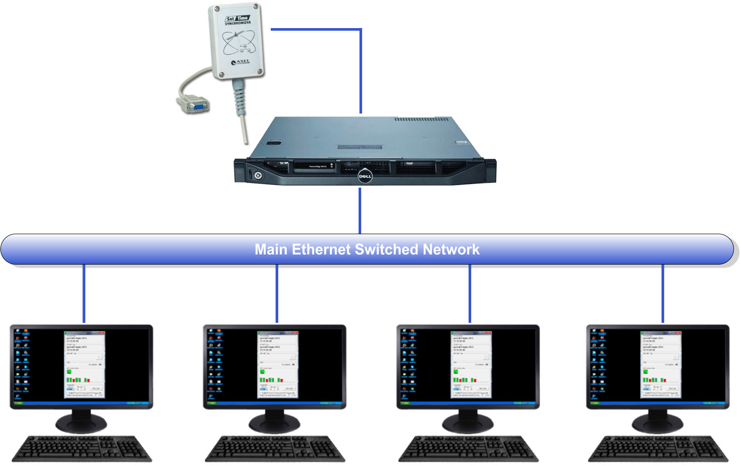
The control software can be installed on any PC running Windows o.s. and featuring a free serial port. The interface shows the main time data and, in graphic mode, the strength of various signals received by GPS. Thanks to the low resources required, the Sat Time Synchronizer software can be installed even on “on-air” PC and workstations.
The current time reference can also be shared among all the PC connected to a LAN. For this aim, SAT TIME SYNCHRONIZER software features a double operating mode and it is able to work both in a “server” version (i.e. for the PC physically connected to the receiver) and in a “client” version (for the networked PCs).
Main Features
- PC clock synchronization from GPS satellite time
- Just a Sat Time Synchronizer unit for the whole PC local network
- Very easy to install
Download the Manual
Axel Tech Academy
Learn moreall our radioWebinars
by Claudio Astorri,Axel Radio Specialist
Axel Tech Academy
Learn moreall our radioWebinars
by Claudio Astorri,Axel Radio Specialist
Ask for aquote now
Subscribe to our newsletter
On Air Clock
Radio
Time Display
The Final Count-down
ON AIR CLOCK displays on standard TV Monitor current time, in six digits HH:MM:SS with circleline seconds. It is used in radio studios, tv studios and master control rooms for correct time display and messaging. Clocks are something you’re always glancing at.
ON AIR CLOCK also displays custom messages, such as “ON-AIR”, “INCOMING TELEPHONE CALL”, “APPLAUSE”, “SILENCE”, providing an additional communication tool besides classic headphone intercom

ON AIR CLOCK offers an unrivalled flexibility of operation, the widest number of functions modes and user display settings. In addition to Time and Date info, two major features are available. - Count-down timer for end of live programs signalling and advertisement interruption during productions. - Count-up timer for live program simulation during recording or just as time elapse display.
On air clock features an android device with HDMI output to connect to a standard TV monitor. Time data and messages are pushed to multiple devices from a central server were the On air clock server is installed.
AxelTech’s Sat Time Synchronizer (optional) may be used as GPS time reference, allowing 1/100 of second accuracy on all ON AIR CLOCK displays.
Main Features
- Simultaneous time and date display
- Fits to any LCD / plasma / TV screen
- GPS time synchronization for 10 msec accuracy(optional)
- Automatic daylight savings change
- Clock / countup timer / countdown timer / message
- Easy signal distribution over cat 5, VGA and coaxg
- GPO alarm triggering / GPI messaging
- User-definable colors and fonts
Axel Tech Academy
Learn moreall our radioWebinars
by Claudio Astorri,Axel Radio Specialist
Axel Tech Academy
Learn moreall our radioWebinars
by Claudio Astorri,Axel Radio Specialist
Ask for aquote now
Subscribe to our newsletter

Mr Light
Radio
On Air Lamp
Mr. Light RGB
MR. LIGHT RGB is the new multipurpose signal lamp designed for Radio, TV, on air, production and recording studios. The lamp is also ideal for any other environment where a signalling light is required such as audio booths, meeting rooms and offices.
It’s highly configurable to match customers’ needs: colour, wording, graphics, brightness and operating mode.
MR. LIGHT RGB has been designed to be easily installed in any environment and condition.

Main Features
Mr. Light RGB
- Multi-coloured RGB LEDs
- Operating mode: blink, blink 2-colours, pulse always on.
- Supplied with mounting kit: wall and ceiling
- Just 1 cable
- GPIs for remote control.
- Easy setting for colour and switching mode
- High availability and low power consumption
- 12V DC power supply included
- Customizable wording with Text and graphics (logos, icons,
symbols and ideograms)
Download the Manual
Axel Tech Academy
Learn moreall our radioWebinars
by Claudio Astorri,Axel Radio Specialist
Axel Tech Academy
Learn moreall our radioWebinars
by Claudio Astorri,Axel Radio Specialist
Ask for aquote now
Subscribe to our newsletter
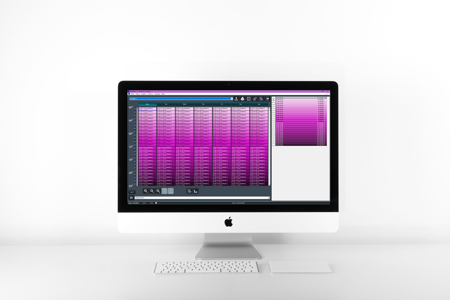
Digiware Radio
Radio
Radio Programs Planning and Music Scheduling Software
High-end Multi-programming
DIGIWARE RADIO is a software for Playlist Management and Radio Program Schedule creation that integrates more intelligence power and many additional features into the DJ-PRO Radio Automation system.
Specially designed to be interfaced with DJ-PRO, DIGIWARE RADIO is a quick, effective way to get the job done. Schedules can be modified in real time up to a few seconds before broadcasting.
DIGIWARE RADIO is the comprehensive tool for music and audio programming: it is available both for multi-user and multi-station setups or single-user and single-station use.
DIGIWARE RADIO is an innovative and effective solution even when it comes to high-end multi-programming, when several Radio stations possibly distributed over many commercial split-zones must be programmed daily and/or at the same time.

- Improved MS-SQL support
- Automatic Podcast generation with triggers
- Pass Order Schedule for Categories
- Improved Jingle data fields, same as Music ones
- Improved Jingle programming, same as Music rules
- Jingle/Song match through rules, for prior or next Song
- New Fuzzy search
- Support Enhancements through Active Directory
- And/Or function added to multi-valuable fields
- Improved wildcard function
- Sequence management with wildcards
- Selectable Audio Timing management in Policies
Driven Planning
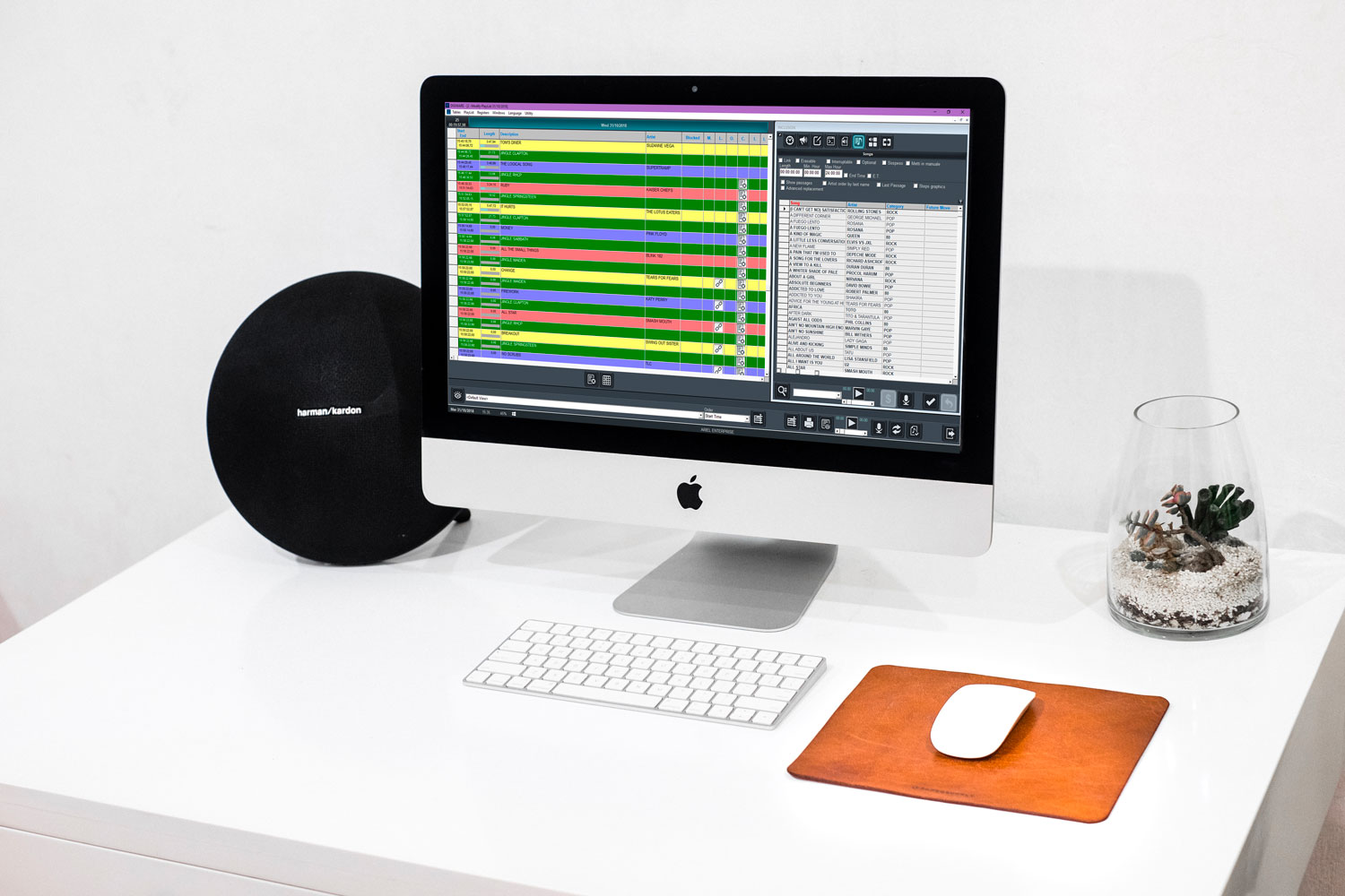
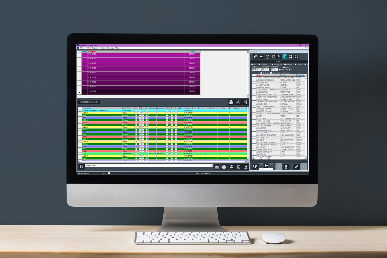
DIGIWARE RADIO graphic interface has been particularly considered: multiple channel schedule with differential commercial split-zone management will result very easy to handle.
DIGIWARE RADIO supports the management of the station’s library composed by songs, promos, pre-recorded programs, news and any bit of audio; the software is also created to assist the integration of live sources, timed events and GPI commands.
The PLAYLIST management is basically achieved thanks to Categories that are used to organize songs and to set their rotation priorities and rules. Categories are then placed into the DIGIWARE RADIO’s Clocks that are among the most flexible in the Radio industry as they can handle any duration and are not limited by the 60 minutes typically fixed hour.
Planning strategies is simple and effective so that powerful rules reflect the actual needs.
DIGIWARE RADIO helps to create the best mix between consistency and variety for the desired format as a balanced music flow keeps the audience tuned. Efficiency and productivity are also increased, allowing more time to focus on further and core aspects of operations, such as selecting music and audio.
DIGIWARE RADIO has been specially designed for the Radio Programmer’s needs; it helps to create Radio schedules automatically and/or edit them manually while it is possible to customize and keep control of all the process steps.
DIGIWARE RADIO assists on programming in the smartest way, creating scheduling that contains audio media totalling up to 24 hours in duration organized in tasks, programmed in a daily, weekly, or season-long airshifts. The scheduler has been created using a “least objectionable” concept via step by step refining, considering also the unavailability of media and the logs created and available at the time of the scheduling creation.
DIGIWARE RADIO is the software partner for those who work in the Music Office of a Radio station or a Radio group. Its services are essential to the workflow; the report section is powerful and contains industry-based licensing forms which saves time and efforts.
Main Features
- Powerful software to manage the complete schedule process.
- Excellent control of Song, Artist and all possible segue/rotation Rules.
- Intuitive creation of format/clocks for any on-air duration.
- Winning tools for both program-driven and flux-based Radio stations.
- Perfect for public or commercial stations, multi-user access with full access-control.
- Graphic interface with icons, CD cover and thumbnails.
- Edit, preview, cue and set marker point runtimes of audio.
- Library, policies, clocks and scheduling quickly by using pre-scheduled elements.
- Charts by rotation, themes, timing or category
- Import and export features from AxelTech’s automation system or from 3rd-party schedulers.
- Audio database direct link with DJPRO CLASSIC and DJPRO ENTERPRISE.
- Copyright and performance printed reports, using customizable or preset formats.
Axel Tech Academy
Learn moreall our radioWebinars
by Claudio Astorri,Axel Radio Specialist
Axel Tech Academy
Learn moreall our radioWebinars
by Claudio Astorri,Axel Radio Specialist
Ask for aquote now
Subscribe to our newsletter
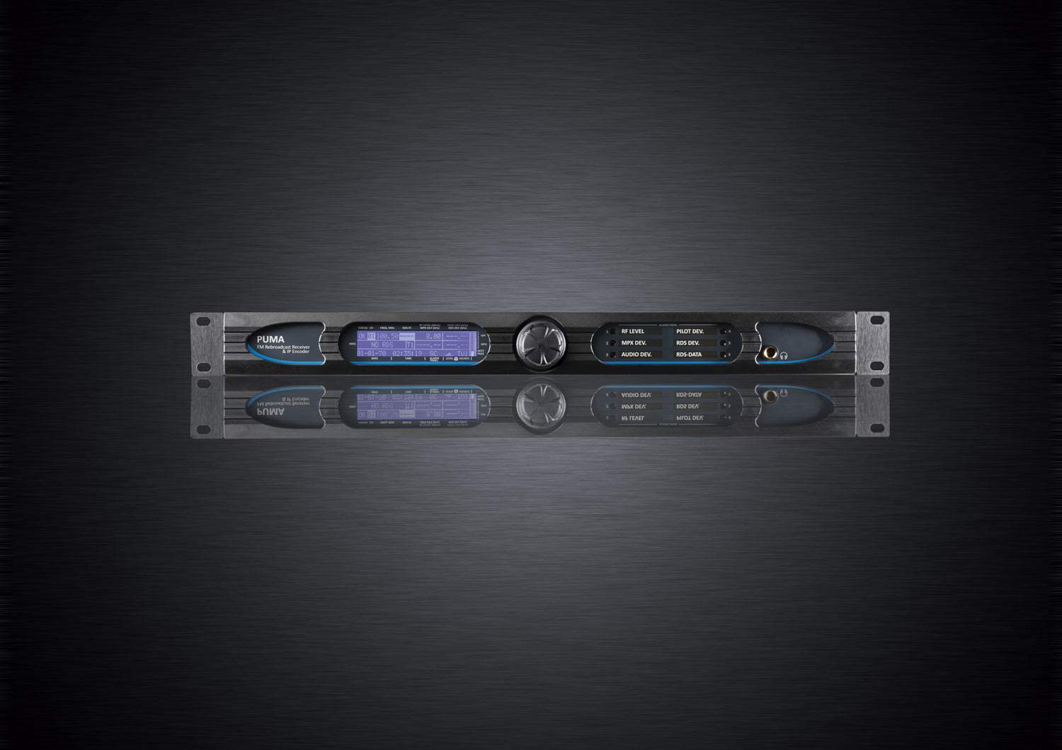
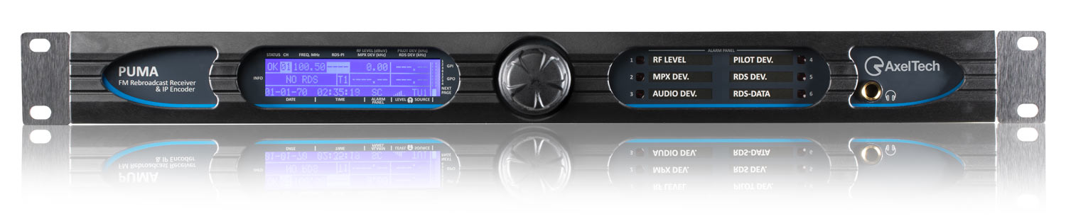
PUMA
Radio
FM Rebroadcast Tuner and IP Encoder
Rebroadcast is a serious matter
Whenever FM broadcasters requires a cost effective solution to deliver and re-broadcast FM content, Puma is the cutting edge, most complete and innovative equipment on the broadcast market.
Puma is high quality frequency-agile FM Re-Broadcast receiver which sets new industry standards in hardware DSP-based radio equipment.
Puma provides RF-FM Monitoring functionalities and an Audio-over-IP encoder in a single equipment. Thanks to its internal digital-based DSP improved FM tuner, Puma returns a complete MPX signal from the received FM frequency. The MPX circuit optimization assures a high quality MPX signal that can be used to feed directly an FM transmitter or a different MPX signal path with amazing MPX performances.
The internal tuner guarantees high performance in FM reception, RF and MPX audio analysis and RDS data stream output.
All captured data during FM channels monitoring can be sent to a Network Management System (such as AxelTech’s
Ranger) or showed in a common web page via SNMP V2 protocol. Once the RF signal is received, audio should be streamed from the transmitter site back to a remote logging system.
Puma is also features an external input source both analog (Left+Right) and AES/EBU. This audio input is continuously monitored: silence detection (Threshold/time and level), left and right presence, peak left, peak right.
Tuner output is available on rear-panel audio connectors on Analog or AES/EBU format .
Puma provides a large variety of additional connections: double Ethernet port, USB and front panel headphone output, 4x
Puma was developed with the latest technology in a fanless hardware format and free of wear parts of any kind. Thorough tests, performed also by end users, showed that Puma circuits are extremely reliable and unaffected by any kind of radiofrequency interferences.

Highlights
- High quality FM Tuner
- RF Frequency agile 87,5 – 108,0 MHz
- Built-In RF, MPX, AUDIO and RDS monitoring system
- RDS decoder and data output in UECP format
- Embedded web server for worldwide consultation
- Audio over-IP streaming, Icecast2 Server, Low bandwidth mode
- SNMP and HTTP web interface and FTP supported
- Double Ethernet ports and double USB interfaces
- High shielded from strong RF fields
- Front LCD display and front panel headphone output
Axel Tech Academy
Learn moreall our radioWebinars
by Claudio Astorri,Axel Radio Specialist
Axel Tech Academy
Learn moreall our radioWebinars
by Claudio Astorri,Axel Radio Specialist
Ask for aquote now
Subscribe to our newsletter
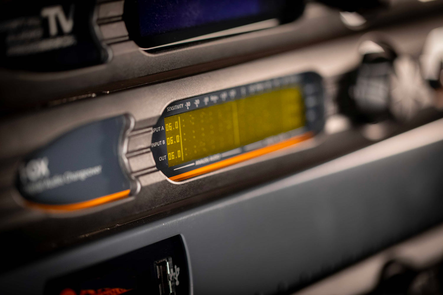
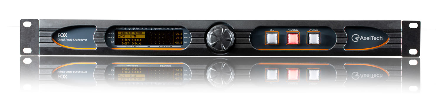
Fox MKII
Fully digital Audio Changeover & Silence Detector
FOX is a fully Digital Audio Changeover & Silence Detector, designed for Radio and TV broadcast
marketplaces.
FOX matches the most High-end broadcast user requirements, with two analog inputs, two digital inputs, one analog output and one digital output.
All inputs can be routed to a different audio output thanks to the A/D and D/A converter, so to manage any kind of switch between different inputs.
Main Features
- Digital Audio Changeover & Silence Detector with 4 inputs and 2
outputs - Broadcast digital DSP-based audio
- 4 Analog/digital inputs and 2 analog/digital outputs with
SRC converter - Any kind of commutation managed by the D/A and A/D
converter - Input to output switch and fade with customizable time
intervention and restore - Denoiser module, AGC stage, input delay and tone
generator - Graphic LCD display and front panel button for monitor
and control - Internal DTMF encoder and decoder for automation
system - 1 Ethernet, 1 RS-232 serial port, 1 USB and GPIO port
Download the Manual
Axel Tech Academy
Learn moreall our radioWebinars
by Claudio Astorri,Axel Radio Specialist
Axel Tech Academy
Learn moreall our radioWebinars
by Claudio Astorri,Axel Radio Specialist
Ask for aquote now
Subscribe to our newsletter
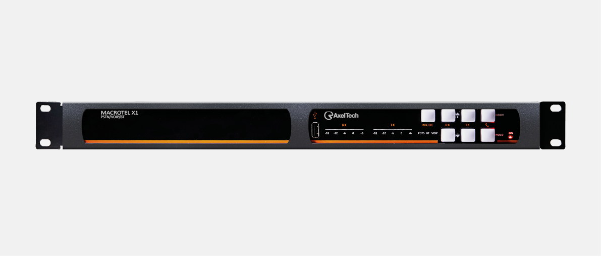
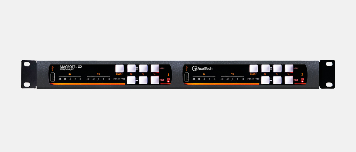
Macrotel X1 - X2
Macrotel X1 & X2GSM/POTS – Digital Telephone Hybrid Processor
Product overview
Macrotel X1 and Macrotel X2 are AxelTech’s Digital Telephone Hybrid third generation designed for a supreme audio quality.
Macrotel X1 manages one POTS/PSTN line while Macrotel X2 can operate on two POTS/PSTN lines.
Moreover, for every landline is available a switching “land-to-wireless mode” through one or two optional Quad Band GSM modules so to establish telephone connection where wired lines are not available.
Macrotel X1 and Macrotel X2’s telephone interface perfectly suits every phone line specs all over the world (country selectable via remote control software).
Models
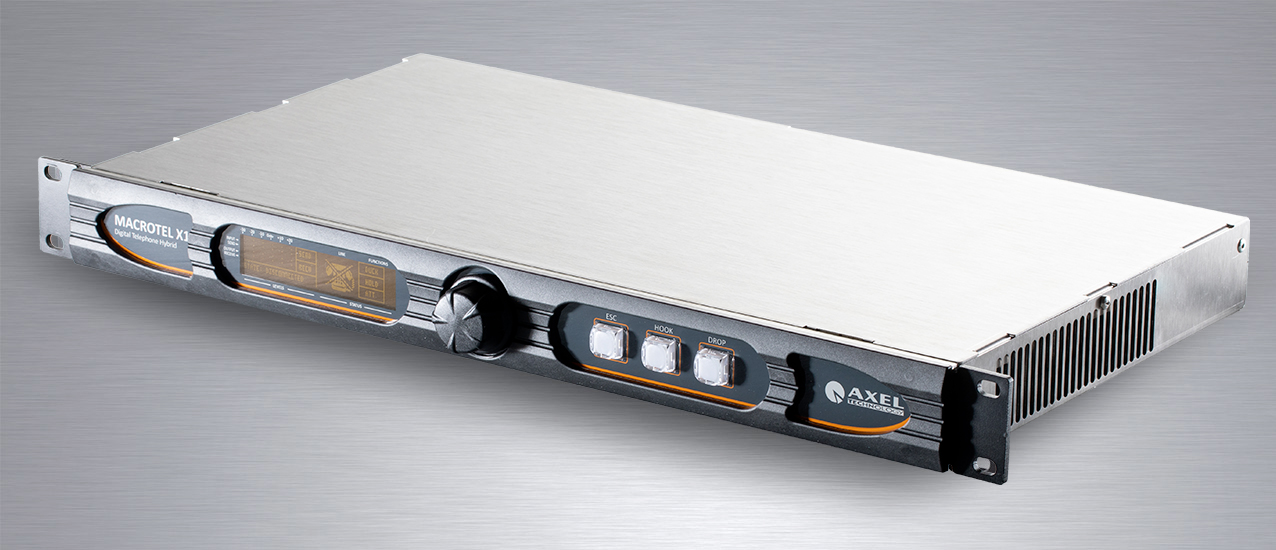
Macrotel X1


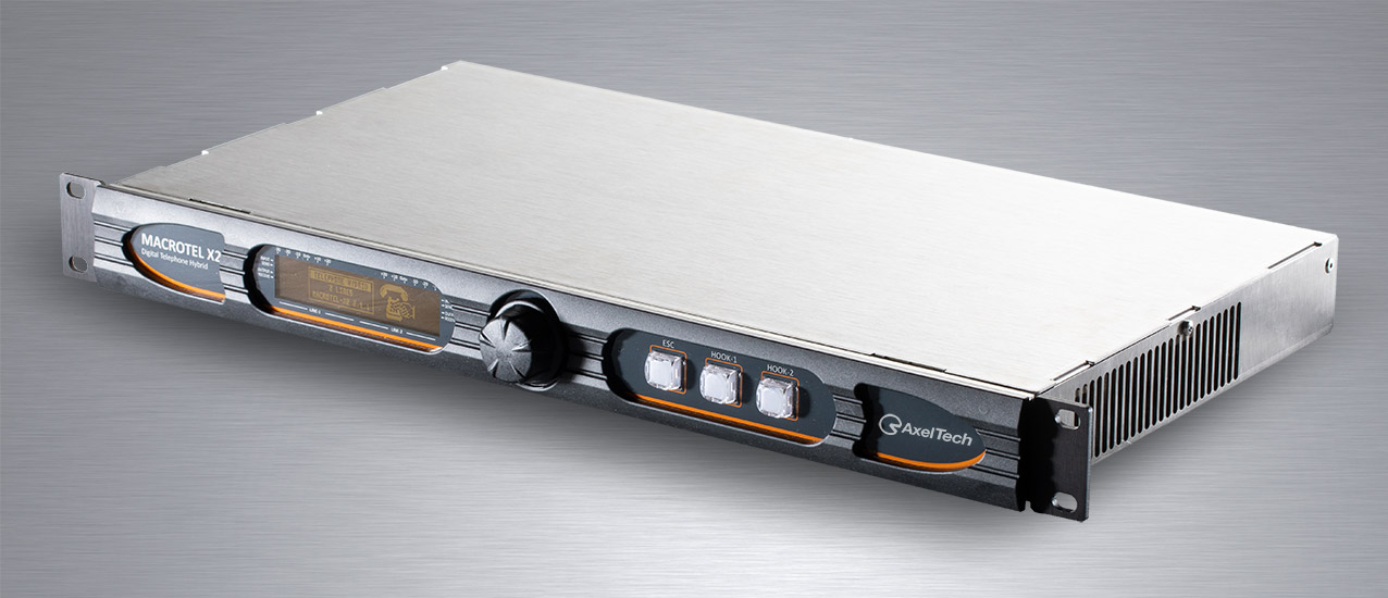
Macrotel X2

Macrotel X1 & X2
Highlights
General
- 1 and 2 line models
- POTS/PSTN and GSM Quad Band (option)
- Digital AGC processor with 2 band EQ
- Echo canceller and noise gate
- Balanced XLR I/O (mic/line)
- Auto answer and disconnection
- Remote control software
- Clear audio and natural sound
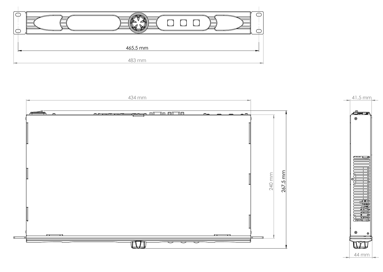
- 19” 1u rack
- Remote control from any mixing console
- Automatic line compensation
- Send/Receive audio level adjustment
- Grafical display
- Direct setting by front panel
- Internal PSU 90-260 Vac 50/60Hz on VDE connector
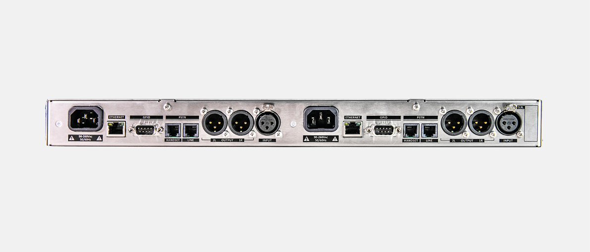
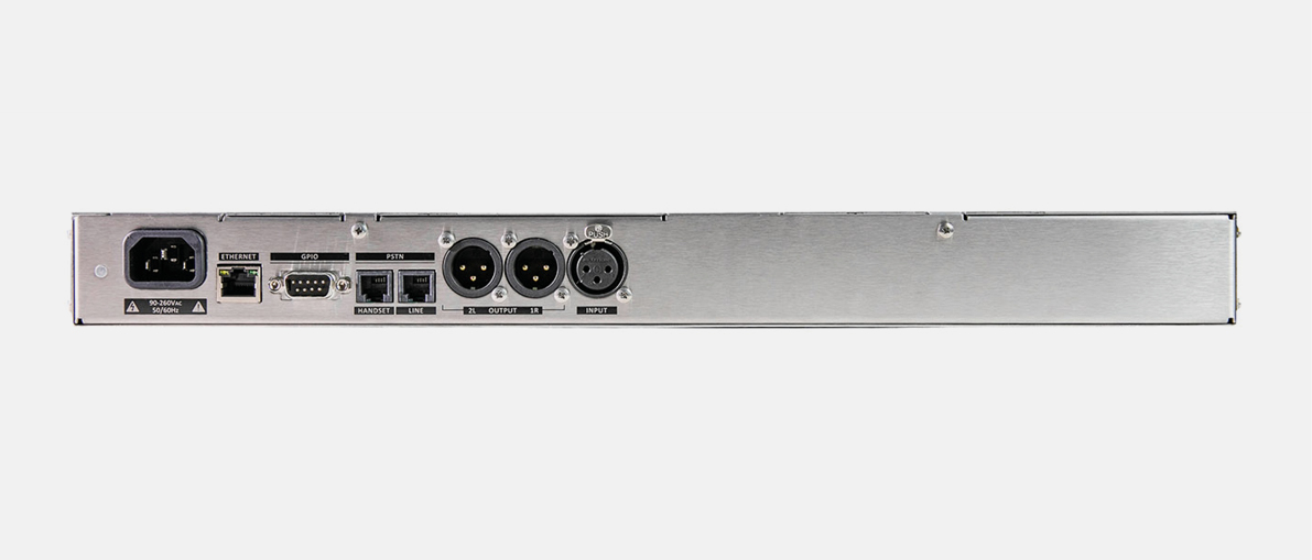
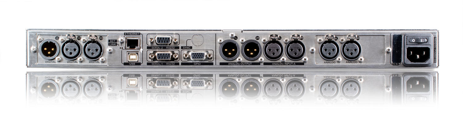
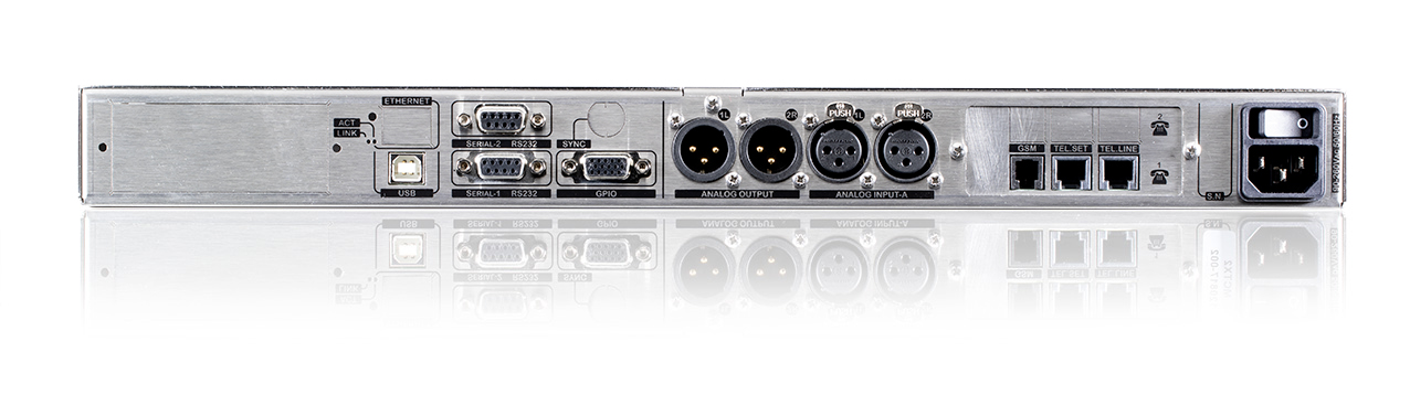
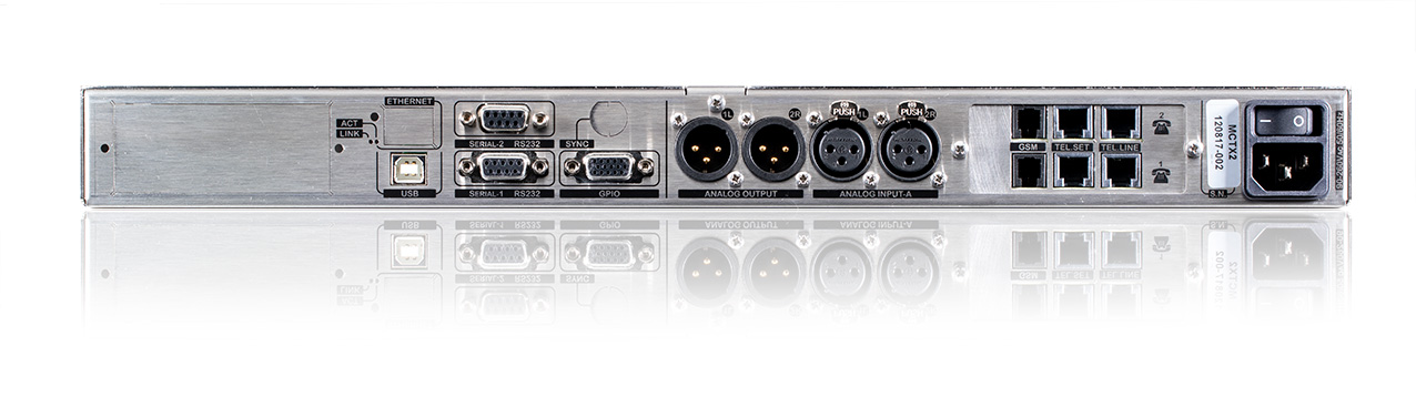
Inputs & Outputs
- 2 Balance analog input on XLR -
- 2 Balance analog output on XLR
- RJ11 connector for POTS line connection (n.2 X2, n.1 X1)
- RJ11 connector for Tel Set connection (n.2 X2, n.1 X1)
- DB15 – 4 GPI and 4 GPO Programmable.
- USB Type B for remote connection
- 2 RS 232 Serial interface on DB9 female connector
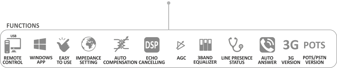
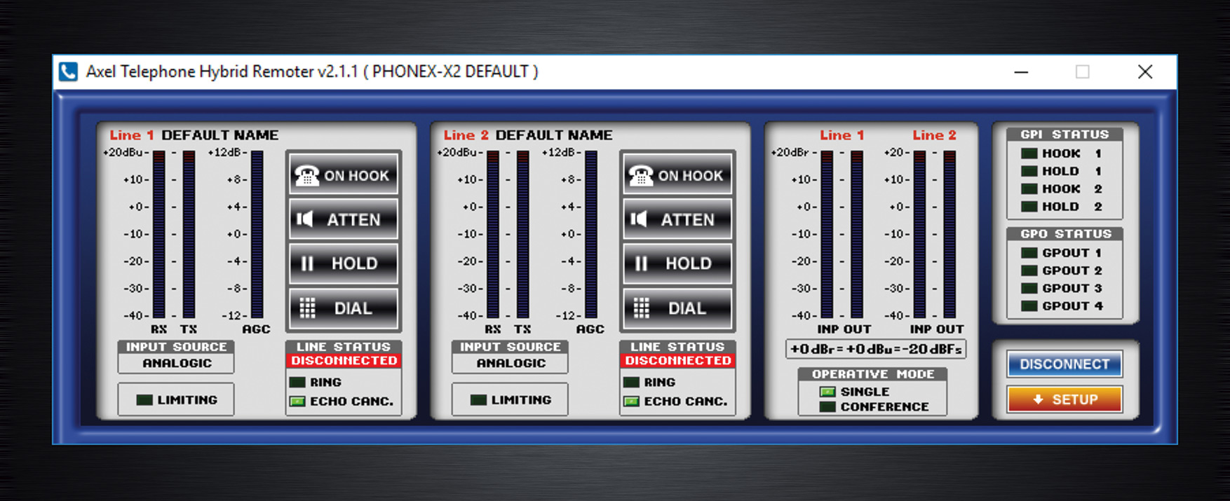
Audio Process and remote control software functions
- Direct managed by SW interface
- RX and TX Telephone Hybrid level meters
- IN and OUT Mixer level meters
- Hook Mode and Drop Mode
- Hold Function
- Nominal Output Level settings (from -10 to +14dB at 1 dB step)
- Conference Function (available only on Macrotel X2).
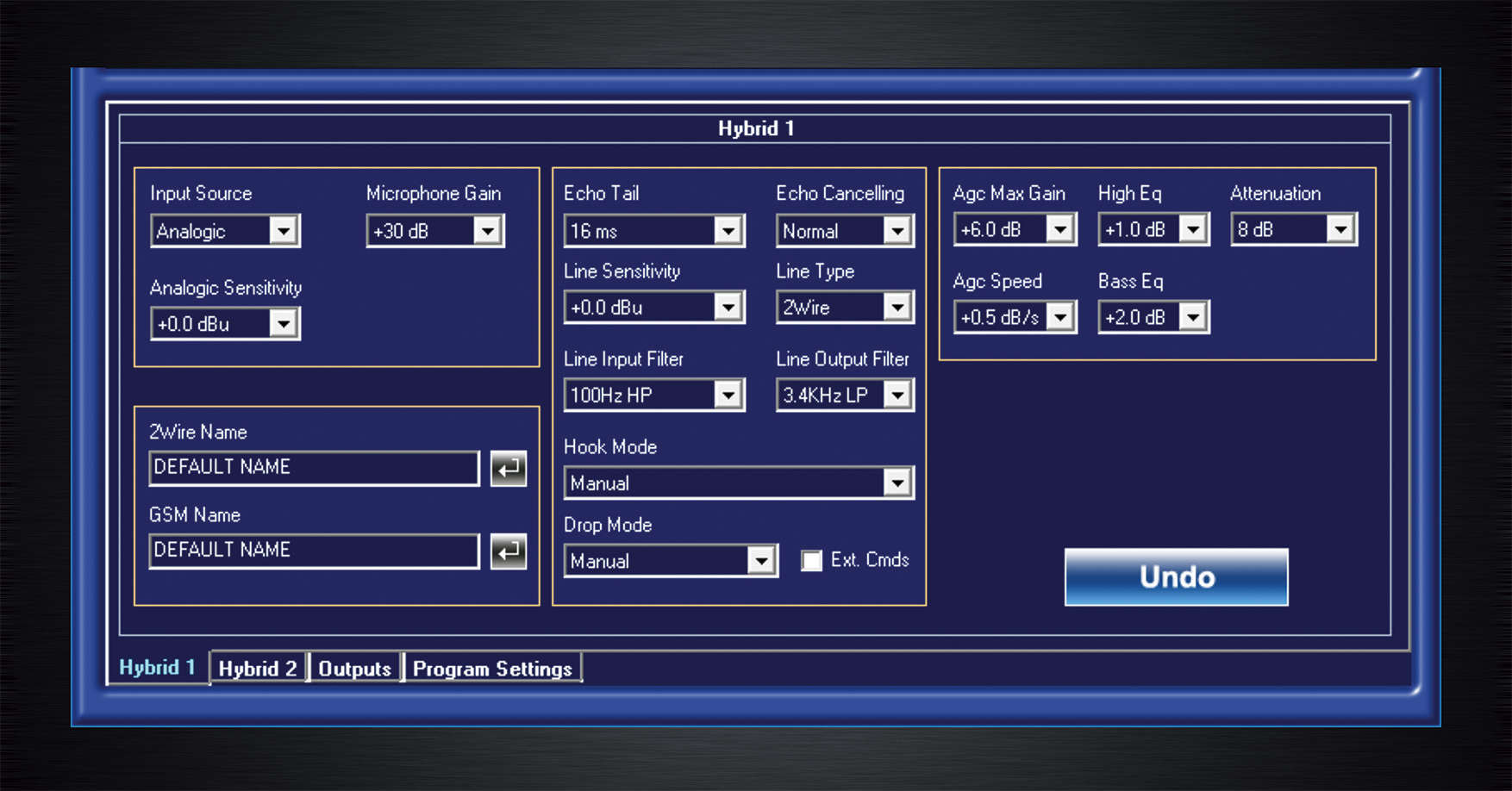
- ATT Function with Attenuation parameter
- Audio Filters (HP and LP)
- AGC settings (Max Gain and Speed)
- Input source mode (Line or Mic)
- Microphone Gain settings (+10 to +40dB at 1 dB step)
- Sensitivity +/-12dB (0.1dB step)
- Echo canceller settings (Echo Tail and Mode)
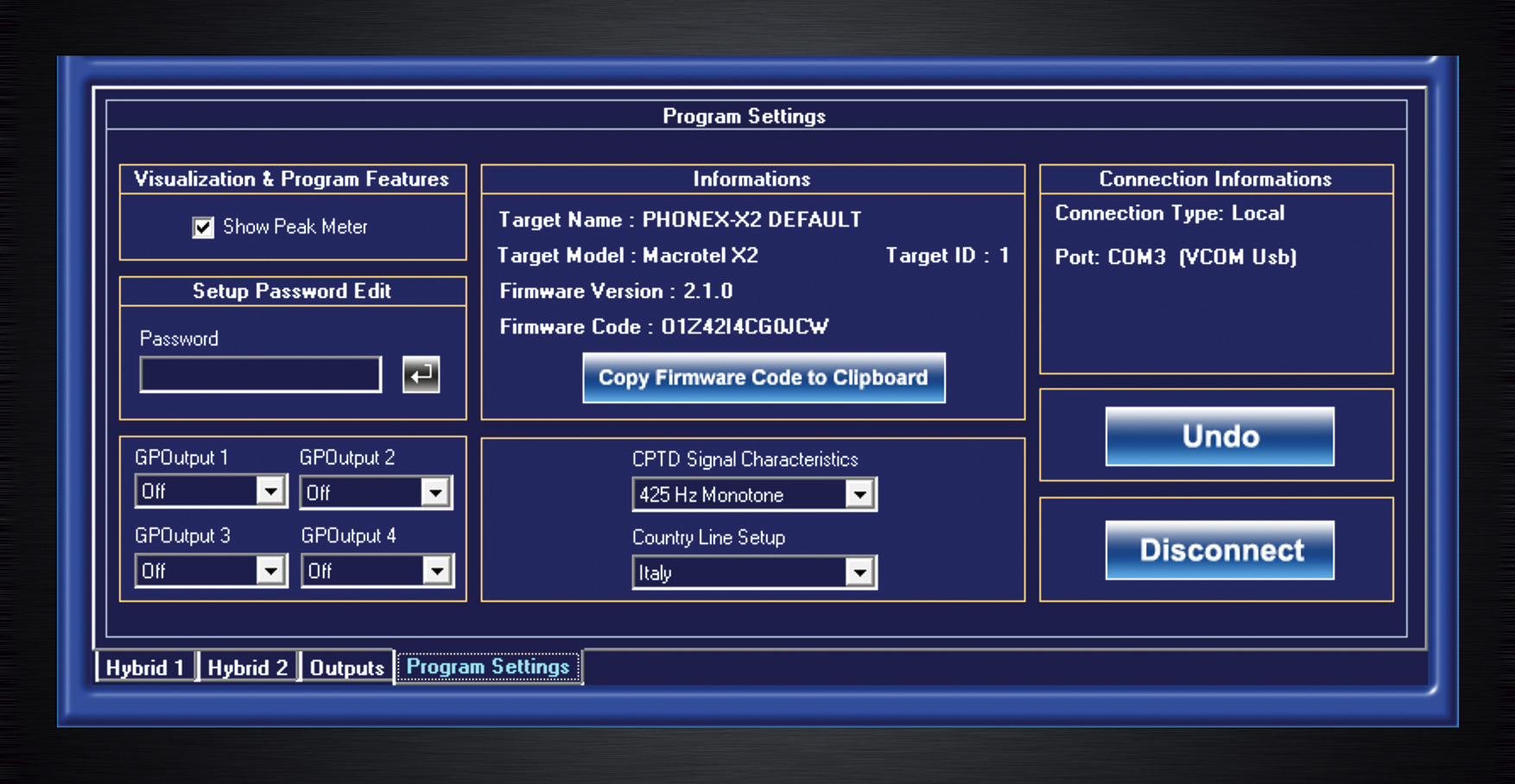
- POTS Line setting (Country, Line Sensitivity, CPDT Characteristic, Label name)
- Equalizer Settings (Hi and Bass freq. From 0 to +12dB)
- GPO 1–4 function settings.
Special Features
The audio processing via DSP together with the automatic gain control (A.G.C) provides a loud and clear receiving level, always steady even when audio caller conditions changes continuously.
Audio controls available on the Macrotel X1 and Macrotel X2 series are: echo canceller with a range from 16 to 32ms, 1 A.G.C stage, 2 Band Equalizer and Attenuator audio feature. Furthermore, the “hold” function allows you to put the caller On Hold before being On Air.
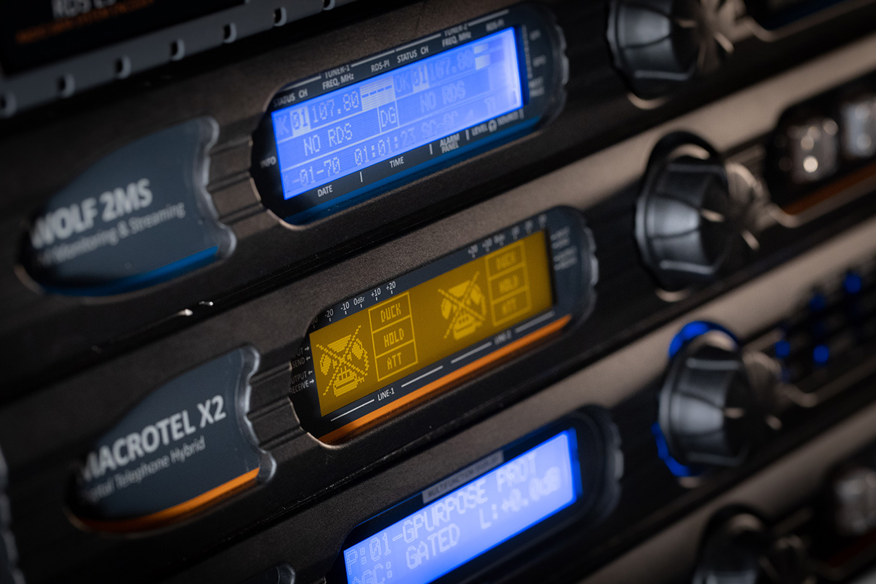
Macrotel X1 and Macrotel X2 front panel controls allow operators to manage phone calls easily, while the graphic display LCD shows Send and Receive audio levels.
The audio inputs and outputs are electronically balanced by XLR connectors; the send input has been designed to be managed as line level or microphone level to match perfectly each user needs. Channels are manageable via USB and Serial connection, or directly from Telco N-1 mixing console modules.
The software manages the phone hybrid operability globally, that means the user can change the working audio parameters and operative mode without any physical action on the equipments.
Auto-ranging internal switching power supply allows to use the equipment all over the world. Macrotel X1 and Macrotel X2 fits 19" standard 1 RU.
Technical Specification
General Features Macrotel X1 Macrotel X2
Lines 1 Pots/Pstn Line or
1 Gsm Line (optional) 2 Pots lines or
2 GSM lines (optional) or
1 Pots line + 1 GSM line (by option)
Phone Line 1x RJ11 6/4 2x RJ11 6/4
Set Line 1x RJ11 6/4 2x RJ11 6/4
GSM Line 1x RJ10 2x RJ10
Line Mode Standard 2-Wire connection or GSM(by option)
Telephone Set mode Worldwide mode, software setup
Audio Features
Audio process 24Bit-120Mhz DSP-Based audio process
A.G.C Fixed - 1 stage
Echo canceller Yes Yes
Attenuator Yes Yes
2-Band EQ Yes Yes
Tone generator 0 dBu @ 800 Hz 0 dBu @ 800 Hz
Dialer keypad Software Yes Yes
Auto call Hook/Drop Yes Yes
Front Panel operation
Hook / drop push button Yes, separate Hook and Drop Yes, same button for Hook and Drop
Ring light Hook-1 push button Hook-1 & Hook-2 push button
LCD Panel 160x32p LCD graphic display
Level Send & receive Showed in LCD graphic display
Audio Input and Output
Send Analog-1 1x XLR female electronically balanced 1x XLR female electronically balanced
Receive Analog-1 1x XLR male electronically balanced 1x XLR male electronically balanced
Send Analog-2 1x XLR female electronically balanced 1x XLR female electronically balanced
Receive Analog-2 1x XLR male electronically balanced 1x XLR male electronically balanced
Microphone Input Software switch Mic/Line
Remote Control
GPIO Connector SubD 15p HD
GPIO Type 4x GP In optocoupled, 4x GP Out Open Collector optoisolated
USB 1x USB – B Type EMI Filtered
Serial 2x Rs232 EMI Filtered
Software Remoter Yes
GSM Wireless module Optional
1 Gsm Line (optional)
2 GSM lines (optional) or
1 Pots line + 1 GSM line (by option)
Dimensions
Ask for aquote now
Subscribe to our newsletter
Wolf 1MS - 2MS
Wolf 1MS & Wolf 2MS
FM Radio Monitoring
Everything under control
Wolf 2MS and 1MS are state-of-the-art FM Radio Monitoring devices, designed to control the signal presence and quality over an FM Distribution Network.
Onboard twin tuners allow to accurately scan frequencies, they offer high performances in FM reception, MPX audio encoding and RDS data streaming. This cutting-edge equipment features three main operating modes: continuously reception, bandscan and smart bandscan.
With FM static mode the user can focus on a single channel, selected and monitored exclusively. Thanks to the scan mode up to 32 channels for each tuner can be scanned and supervised in a single analysis. FM static mode also receives up to 64 memories. Wolf 1MS and 2MS allow to manage accurately RF, MPX, RDS, Audio and RDS data dynamic services. In smart mode the channel scan time is adjusted automatically according to instantaneous measurements requirements.
Wolf 1MS and 2MS are the ideal Probes for a Network Management System.
All data and information captured during the FM Monitoring can be collected by a Control Room and used to analyse the FM Network performances in real-time or in the past.
Models
For simple configurations that do not require NMS software, Wolf can send via email a daily report of the 24 hours events. Wolf provides a database sheet to manage these information. The two built-in audio streamers are the essential feature of Wolf 2MS (Wolf 1 MS has 1 built in audio streamer). Audio channels can be streamed to a remote logging system that records both, audio and data, coming from the transmitter site. It is also possible to send audio stream to a remote player for audio-on-demand purposes. Users can listen to each single FM tuner and streamed audio anywhere, using all Internet browsers.
Two onboard network interfaces provide maximum flexibility in streaming and connectivity processes. From PCs, tablets and smartphones broadcasters can completely control Wolf and have full access to all data and alarms. When an alarm is trigged, NMS system sends notifications via SMS or email or takes an action to manage any possible issue.
External input sources are available: analog Left + Right and digital AES/EBU inputs. Users can connect audio to the controlled external input sources. These audio inputs are constantly monitored: silence detection, and audio presence. Tests, performed also by end users, have shown that Wolf circuits are extremely safe and completely free from any kind of radiofrequency interference.
Wolf 1MS

Wolf 2MS
Highlights
General
- Real time measurements for FM networks, fully digital
- Wolf 1 MS: single FM Tuner and single audio over-IP streaming for monitoring
- Wolf 2MS: double FM tuner and double audio over-IP streaming for monitoring
- More than 30 alarms for any frequency received (Wolf 2MS 64. Wolf 1 MS 32)
- Fully independent time, Thr, Hysteresis, for any frequency parameter
- Configurable bandscan for each FM tuner
- Embedded web server for worldwide consultation
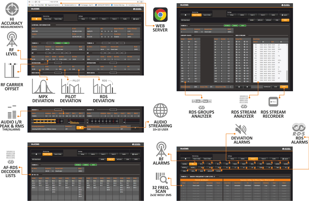
- Analysis modulers: RF, MPX, audio and RDS
- RDS decoder with group sequence decoding for each tuner
- SNMP and HTTP web interface and FTP supported
- Double ethernet ports and double USB interfaces
- Front LCD display
- Front panel headphone output
- Analog auxiliary input and AES/EBU
- Main Supply 90--260Vac 50/60Hz. 25W
- Graphic display
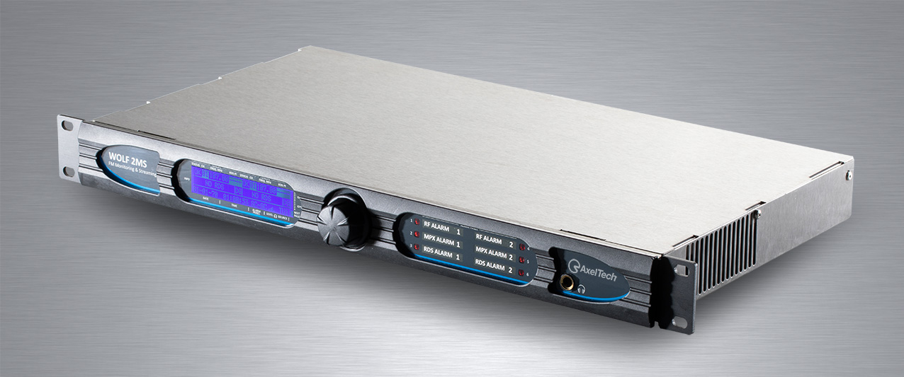
- Form factor: 1RU 19” - Inox steel
- High immunity to strong RF fields, designed to be installed in high power TX sites
- Fully programmable by a simple and intuitive Web GUI interface
- Headphones output with level control
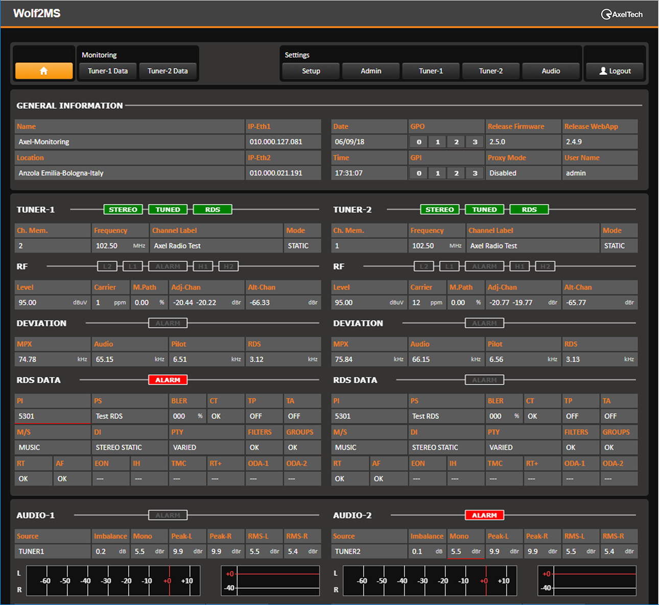
Monitoring Parameters
- RF parameters:
- RF level, Carrier offset, Multipath, Adjacent carriers level (+/- 100kHz), Alternative carriers level (+/- 200kHz)
- Deviation parameters
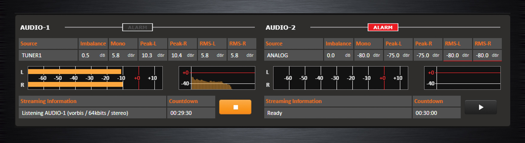
- MPX level, Audio level, Pilot level and RDS level
- Audio parameters
- Inbalance L/R, Mono, Peak left, Peak right, RMS left, RMS right, MPX power
- RDS parameters
- PI, PS, BLER, CT, TP, TA, M/S, DI, PIN & PTY (Day/Hour/Min/PTY), FILTERS, GROUPS, RT, AF, EON, IF, TMC (AID/Group/Data), RT+(AID/Group/Data), ODA-1(AID/Group/Data), ODA-2(AID/Group/Data), LA, EG, ILS, LSN, SLC0-SCL7
- 64 list of 25 frequencies always decoded
- 10 EON for each frequency received with PI, PS, PIN (date, hour, minute) PTY, TP, TA, LA EG, ILS, LSN, AF
- Received groups stats 0A-15A, 0B-15B
- RDS Stream with groups filters with download function
Communications & Management
- Ethernet/USB/RS232/GPIO connections
- SNMP V2c
- NTP Address for Time and Date synchronization
- 1 RS232 for RDS UECP data streaming
- 4 GPI and 4 Relay (DB 15p F HD)
- 2 USB A-Type
- HTTP, FTP, SNMP, SMTP, UDP, TCP support
- Alarms via: TRAP (SNMP), email(SMTP), GPO, HTTP
- uSD Card for clone function, for maintenance and easy replace of a faulty unit
- Import and export configurations function
- Logs 24/7 with export functions
- Right access management
- Easy configuration page setup with info connection diagrams
- Multi-user contemporary acces
Inputs & Outputs Audio
- Balanced analog input on XLR
- Balanced analog output on XLR
- Balanced digital AESEBU input on XLR
- Balanced digital AESEBU output on XLR
Alarms & Parameters
- Silence detector on analog input
- Silence detector on digital input
- 4 alarm on RF level with 4 Thr (RFL2, RFL1, RFH1, RFH2).
- Deviation level (Thr, Hysteresis, Validation Time and Hold Time, Mask, Label, Email and Trap enable)
- Pilot low level (Thr, Hysteresis, Validation Time and Hold Time, Mask, Label, Email and Trap enable)
- Pilot window (Thr Min, Thr Max, Hysteresis, Validation Time and Hold Time, Mask, Label, Email and Trap enable)
- RDS low level (Thr, Hysteresis, Validation Time and Hold Time, Mask, Label, Email and Trap enable)
- RDS window (Thr Min, Thr Max, Hysteresis, Validation Time and Hold Time, Mask, Label, Email and Trap enable)
- Audio deviation silence (Silence Thr, Validation Time and Hold Time, Mask, Label, Email and Trap enable)
- Audio left deviation silence (Silence Thr, Validation Time and Hold Time, Mask, Label, Email and Trap enable)
- Audio right deviation silence (Silence Thr, Validation Time and Hold Time, Mask, Label, Email and Trap enable)
- Audio mono level (Thr, Validation Time and Hold Time, Mask, Label, Email and Trap enable)
- Audio stereo in-balance level (Avg, Thr, Validation Time and Hold Time, Mask, Label, Email and Trap enable)
- RDS-PI (PI-1, PI-2, PI-3, Validation Time and Hold Time, Mask, Label, Email and Trap enable)
- RDS-PS (PS-1, PS-2, PS-3, PS-4, Wild Char, Validation Time and Hold Time, Mask, Label, Email and Trap enable)
- RDS-TP (Ref, Validation Time and Hold Time, Mask, Label, Email and Trap enable)
- RDS-TA (MaxOnTimeout, NoVarTimeout, Mask, Label, Email and Trap enable)
- RDS-CT (Timeout, Max Offset, Mask, Label, Email and Trap enable)
- RDS-RT (Timeout, Hold Time, Mask, Label, Email and Trap enable)
- RDS-AF (Validation Time, Hold Time, Mask, Label, Email and Trap enable)
- RDS-EON (Validation Time, Hold Time, Mask, Label, Email and Trap enable)
- RDS-IH (Data Timeout, Group Timeout, Hold Timeout, Mask, Label, Email and Trap enable)
- RDS-TMC (Reg. Timeout, Data Timeout, Hold Timeout, Mask, Label, Email and Trap enable)
- RDS-RT+ (Reg. Timeout, Data Timeout, Hold Timeout, Mask, Label, Email and Trap enable)
- RDS-ODA-1 (AID, Reg. Timeout, Data Timeout, Hold Timeout, Mask, Label, Email and Trap enable)
- RDS-ODA-2 (AID, Reg. Timeout, Data Timeout, Hold Timeout, Mask, Label, Email and Trap enable)
- RDS-BLER (Max, Hysteresis, Validation Time, Hold Time, Mask, Label, Email and Trap enable)
- RDS-GROUPS (Group mask, Timeout, Validation Time, Hold Time, Mask, Label, Email and Trap enable)
- RDS Filters (Block-1 Mask Ref., Block-2 Mask Ref., Block-3 Mask Ref., Block-4 Mask Ref., Timeout, Validation Time, Hold Time, Mask, Label, Email and Trap enable)
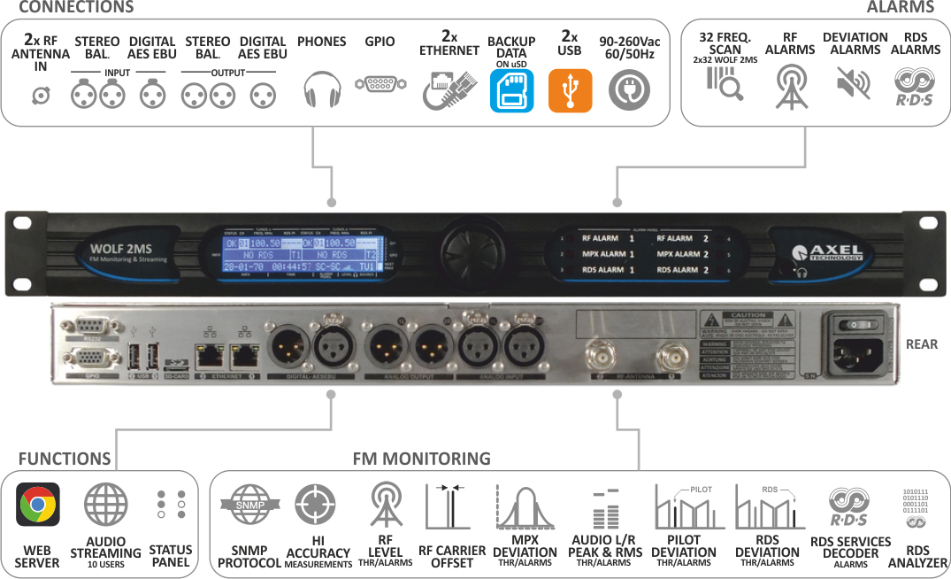
Block Diagram
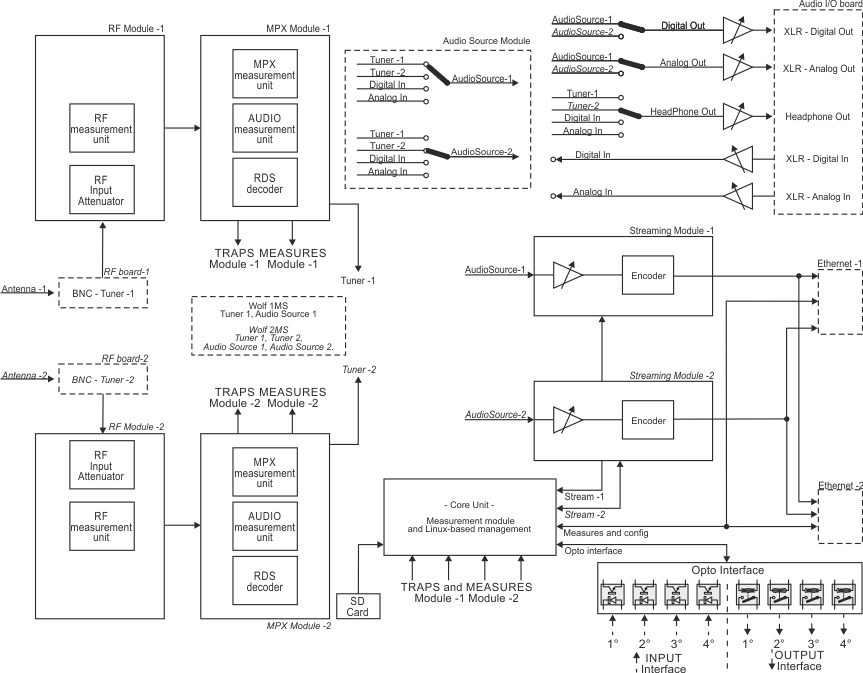

Wolf 1MS and Wolf 2MS are FM monitoring systems designed for FM Off Air signal monitoring purpose. Wolf 1MS is provided with one high quality FM tuner, while Wolf 2MS allows the broadcaster to receive up to two frequencies thanks to an internal double tuner. Tuners are independent and they can operate in three ways: Continuous reception, Bandscan and SmartScan.
Internal tuner ensures high performances in FM reception, RF and MPX audio analysis and RDS data stream output. The monitoring made on FM channels can be a basic RF analysis or an advanced RF, MPX and AUDIO measurement.
- Continuous reception: a single carrier is selected and monitored;
- Bandscan mode: 32 FM Channels can be scanned and monitored in Wolf 1MS and 64 FM Channels can be scanned and monitored in Wolf 2MS. The bandscan time is also user definable, in a range from 1 second up to 10 seconds for each channel;
- SmartScan mode allows a smart and variable scan time that is adjusted automatically to fit the instantaneous measurement requirements. Thanks to this feature it is possible to avoid false-positive rising errors.
Special Features
During continuous reception mode, each single tuner checks and completely decodes the multiplexed signal:
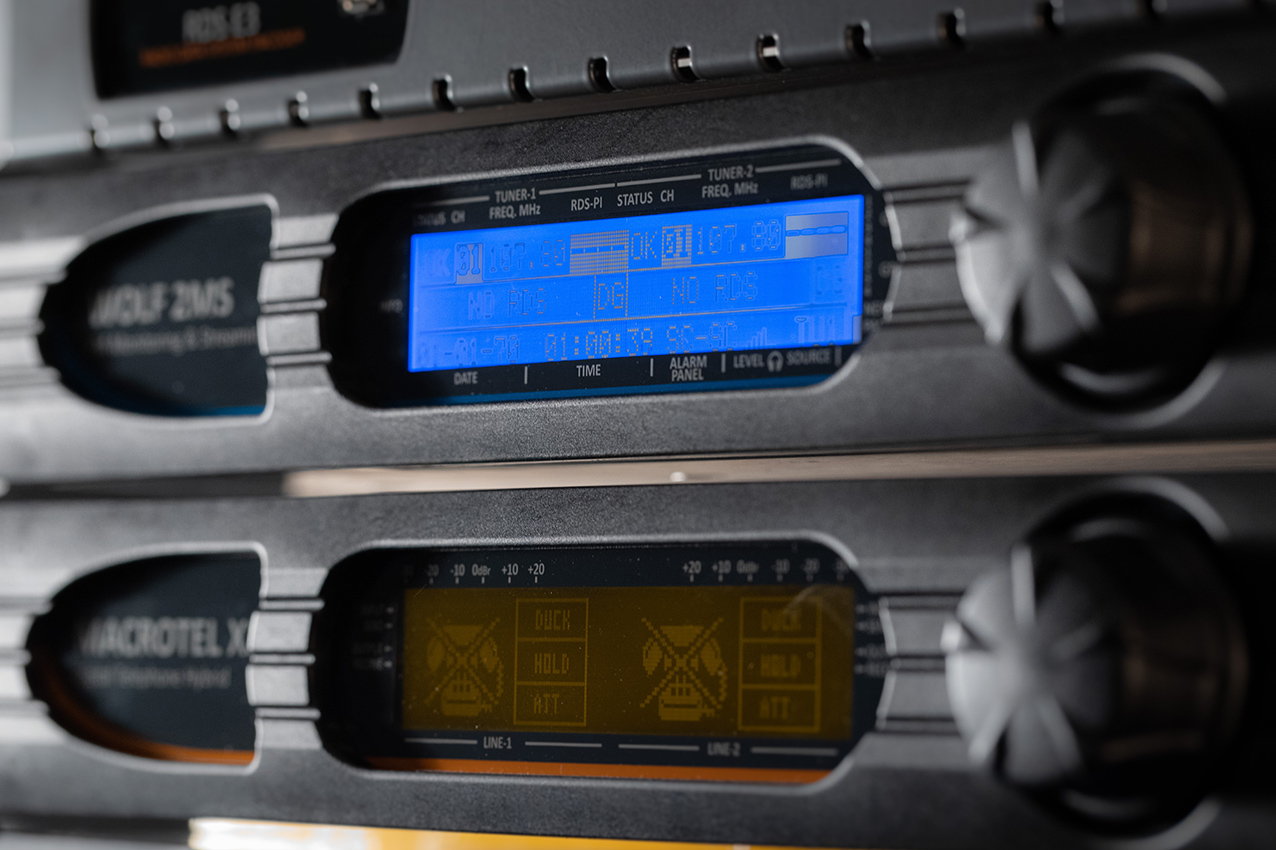
Mono level, Pilot level, Audio and RDS levels are measured and they are always under control. All datas, captured during FM Channel monitoring, can be sent to a Network Management System (such as AxelTech’s Ranger) or they can be shown in a common password protected web page. Communication between Wolf and Ranger NMS is SNMP v2C protocol. For all single parameters under monitoring, a threshold can be set. If one or more values go out of range, alarms are delivered.

Once the RF signal is received, audio should be streamed from the transmitter site back to a remote logging system. The streamer input allows to do an internal selection between all inputs available: Tuners, External Analog In, External AES/EBU In.
Wolf 1MS and Wolf 2MS are completed with an “External Input” source: analog Left + Right input and Digital Left + Right in AES/EBU format. This audio input is continuously monitored: silence detection (Threshold/time and level), left and right presence, peak left, peak right. Rear-panel audio output always presents the audio decoded from Tuner-1 or Tuner-2 and this setting is user definable, while audio is available on analog or AES/EBU format.
Wolf 1MS and Wolf 2MS provide a large variety of connection: double Ethernet port, USB and front panel headphone output, 4x GPIn opto coupled and 4x GPOut over relays. Rs232 serial port for RDS-UECP bridging and rebroadcasting purposes, and rear panel placed SD card to store or recall the complete equipment configuration.
RF antenna inputs are over BNC connectors, a XLR balanced stereo analog input and output, AES/EBU input and output. OS and datas are loaded and stored over solid state memory as SD and flash RAM. Universal switching power supply, 1 rack unit space in fan-less configuration, allows to operate worldwide.
Measures
Field Type of measure Description U.M.
RF 4x RF Level lower threshold Measure, alarm via email/trap SNMP dBµV
2x Adjacent channel L1 threshold Measure, alarm via email/trap SNMP
Alternative channel - Worse Measure dBr
Carrier precision Measure ppm
Multi path Measure %
MPX Deviation max Measure, alarm via email/trap SNMP kHz/dBr
2x Pilot lower level - 2 threshold level Measure, alarm via email/trap SNMP
MPX power – ITU-R BS.412 Measure, alarm via email/trap SNMP
RDS Level RDS level lower threshold Measure, alarm via email/trap SNMP
RDS level higher threshold Measure, alarm via email/trap SNMP
Audio Peak left - Peak right threshold Measure, alarm via email/trap SNMP dBr
RMS left - RMS right threshold Measure, alarm via email/trap SNMP
Audio imbalance – L/R delta threshold Measure, alarm via email/trap SNMP
Mono silence – L+R threshold Measure, alarm via email/trap SNMP
Audio MPX deviation threshold Measure, alarm via email/trap SNMP kHz
Audio MPX Silence detection threshold Measure, alarm via email/trap SNMP
s
Audio left – Right silence det. threshold Measure, alarm via email/trap SNMP
RDS Data AF - Complete decoding + Visualization
PS – 4 PS matching reference
PI – 3 PI Code matching reference
CT – Time offset
DI – Decoder information
PTY – Program type
TP/TA – timeout TA
M/S – Music speech
BLER – Block error rate
TMC – AID – Group – Data
EON Enhance other channel
RT – RT+ data decoding
LA – EG – ILS – LSN-PIN
ODA TMC
ODA RT+
ODA - 1 ODA - 2
SLC0 - SLC1 - SLC2 - SLC3 - SLC4 - SLC5 - SLC6 - SLC7
RDS Data decoding group, visualization and storage. Alarm generation in case of error, can be shown in a common web page or delivered via email.
Interfacing with up to 4 NMS allows equipment to deliver traps using SNMP protocol.
Technical Specifications
PARAMETERS DESCRIPTION
Main Power 100 Vac - 240 Vac 50/60 Hz internal, universal power supply
Power consumption 25 W
Power connector IEC plug filter with internal fuse 2.0 AT
Headphones Stereo Jack 6.3 mm
Safety and EMC Compliant to CE laws
Working temperature 0° to 50° C (storage -5 to + 50 °C)
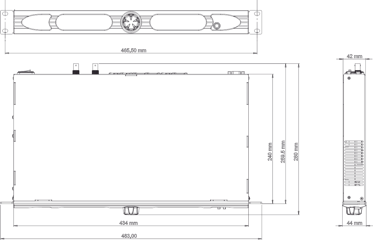
Housing dimensions 19 inch x 1u x 240 mm (depth)
Weight 3.5 kg
RF TUNERS
Tuner frequency 87.5 MHz ‐ 108.0 MHz
Tuner step 10 kHz
RF tuning stability +/- 500 Hz
RF input sensitivity 20 to 120 dBµV
RF input nominal level 80 to 100 dBµV
RF inputs main 2x BNC, with 50 Ohm unbalanced
Max frequency deviation 125 kHz
IF filter bandwidth 34 kHz to 138 kHz – Manual or automatic
Input RF level 30 dBµV – 120 dBµV with internal attenuator
Bandscan carrier number 32 channels
Bandscan time Static Mode, Scan 2s to 20s and Smart Mode*
Selectivity at ± 120 kHz > -3 dB
Selectivity at ± 200 kHz > -40 dB
Selectivity at ± 300 kHz >- 50 dB
Selectivity at ± 400 kHz >-65 dB
Image rejection @ 22.5 kHz 70 dB
Adjacent channel rejection 63 - 65 dB
Alternate channel rejection 65 - 72 dB
THD @ dev=75 kHz 0.05 – 0.1 %
Mono (S+N)/N 75 dB typ – 68 dB min (No A-Weighting 30 Hz – 15 kHz)
STEREO DECODERS
Stereo (S+N)/N
61 dB Stereo/61 dB mono @ 40 dBµV
65 dB Stereo @ 50 dBµV
80 dB Stereo @ 70 dBµV
Pilot 19kHz suppression 55 dB (Stereo modulation L = 1, R = 0,Deviation=67.5 kHz, Pilot deviation=6.75 kHz)
Stereo THD + N Measures @ 70 dBuV with 75 kHz deviation
100 Hz - 0.055 %
1 kHz - 0.061 %
5 kHz - 0.19 %
10 kHz - 0.46 %
Stereo separation 45 dB (Stereo modulation L = 1, R = 0,Deviation=67.5 kHz, Pilot deviation=6.75 kHz)
48 dB @ 400 Hz
48 dB @ 1 kHz
48 dB @ 5 kHz
38 dB @ 10 kHz
38 dB @ 14.7 kHz
RDS DECODER
RDS sensitivity 20 dBµV (dev f = 2 kHz, RDS BLER < 5%)
RDS synchronization time 80 ms (dev f = 2 kHz RF input = 60 dBµV)
RDS PI lock time 100 ms (dev f = 2 kHz RF input = 60 dBµV)
RDS data decoding and streaming RDS level indication and deviation (voltage, kHz and dBr)
RDS data decoding services PS, PI, M/S, DI, TP, TA, AF, AF List Presence A/B Method, Scrolling PS, AF EON, Radio Text, Radio Text Plus, CT, PTY, PIN, IH, TMC, EWS, TDC. ODA generic services. RDS error detection with three shold adjustable
RF MEASUREMENT MODULE Ranges – Resolution - Precision
RF Level 0 – 80 dBµV (resolution 1 dBµV, precision 2 dBµV)
82 – 120 dBµV (resolution 2 dBµV, precision 5 dBµV)
Deviation 0-125 kHz (resolution 1 kHz, precision 2 kHz)
Tuned carrier frequency offset 0-250 ppm (resolution 2 ppm, precision 5 ppm)
Multipath 0-100 %
Adjacent channel RF level 0 – 80 dBµV (resolution 1 dBµV, precision 2 dBµV) (+-200kHz)
MPX MEASUREMENT MODULE Ranges - Resolution - Precision
Pilot level 0-20 kHz (resolution 0.1 kHz, precision 0.2 kHz)
Rds level 0-20 kHz (resolution 0.1 kHz, precision 0.2 kHz)
Mpx power ITU-R-BS412 (Estimated) -20 dBr to + 12 dBr (resolution 0.1 dBr, precision 0.5 dBr)
Stereo Valid Stereo signal detector
AUDIO MEASUREMENT MODULE Ranges – Resolution – Precision
Left Quasi Peak Programmable attack time from 0 mS to 2 mS (Resolution 0.1 dB)
Right quasi peak Programmable attack time from 0 mS to 2 mS (resolution 0.1 dB)
Audio silence Threshold - 80 dB to 0 dB, Time: 1-120 Sec
Unbalanced stereo signal Threshold - 80 dB to 0 dB, Time: 1-120 Sec
AUDIO OUTPUT
Available output on XLR Tuner - 1 or Tuner - 2, definable via web page. Same audio on analog and AES/EBU
Audio frequency response 30 Hz - 15 kHz, ± 0,3 dB
Phones (Front panel) Stereo jack 6.3 mm, 150 Ohm, 0.8 W
ANALOG OUTPUT MODULE
D/A Conversion 24bit Sigma - Delta conversion - 32 kHz Sample rate
Connectors 2x XLR, male - Electronically balanced
Output level -12.0 dBu to +14.0 dBu (0.1 dBu Step) - Max (+20 dBu)
Impedance Source 47 Ω
Load impedance 600 Ω or greater
Distortion Less than 0.02% TDH + Noise (0.0dBu @ 1Khz)
Dynamic range 108 dB (110 dB A-weighted, 20Hz - 15kHz)
Sources Streamer1_Source , Streamer2_Source
DIGITAL OUTPUT MODULE
Connectors: XLR, Male - Electronically balanced
Format AES3/EBU
Sample rates 32 kHz
Resolution 24 bits
Operative nominal level: From 0.0 dBFs to - 24dBFs (0.1 dBu step)
Dynamic range: 125 dB (Typ), 122 dB (Min)
Distortion less than 0.01% TDH+NOISE (-20dBFs @ 1Khz)
Freq. response 20Hz -15kHz
Dynamic range 108 dB
Sources Streamer1_Source , Streamer2_Source
AUDIO INPUT
Encoder streaming input source User selectable between Tuner-1, Tuner-2, External Input Analog, External Input AES/EBU
DIGITAL INPUT MODULE
Connectors: XLR, female – Electronically balanced
Format AES3/EBU
Sample rates 32 kHz/44.1 kHz/48 kHz/96 kHz with src and jitter correction
Operative nominal level: From 0.0 dBFs to - 24dBFs (0.1 dBu step)
Dynamic range: 125 dB (Typ)
Distortion less than 0.01% TDH + Noise (-20dBFs@ 1Khz)
Input modes: Stereo, Mono (Left), Mono (Right), Mono (Left + Right)
ANALOG INPUT MODULE
A/D conversion 24bit Sigma - Delta conversion - 32kHz sample rate
Connectors: XLR, female - Electronically balanced
AD clipping point +20.0dBu
Operative nominal level: From - 12.0dBu to +12.0dBu (0.1dBu Step)
Line impedance 10 kΩ (Electronically balanced selectable) EMI - suppressed
Distortion: less than 0.02% TDH+NOISE (0.0dBu @ 1kHz)
AD dynamic range: 108 dB RMS (110 dB A - weighted, 20Hz - 15kHz)
Input modes: Stereo, Mono (Left), Mono (Right), Mono (Left + Right)
AUDIO & RDS STREAMING MODULES
Protocols UDP/RTP, TCP/IP, IceCast2
Encoders OGG - VORBIS
Interface Ethernet port 10/100 Mb/s
Bitrate User select 24 kbps to 192 kbps
Sample rates 32Ksamples/sec
RDS streaming Proprietary redundant protocol over UDP or RAW-TCP/IP
Administration User right management
Dimensions
Ask for aquote now
Subscribe to our newsletter
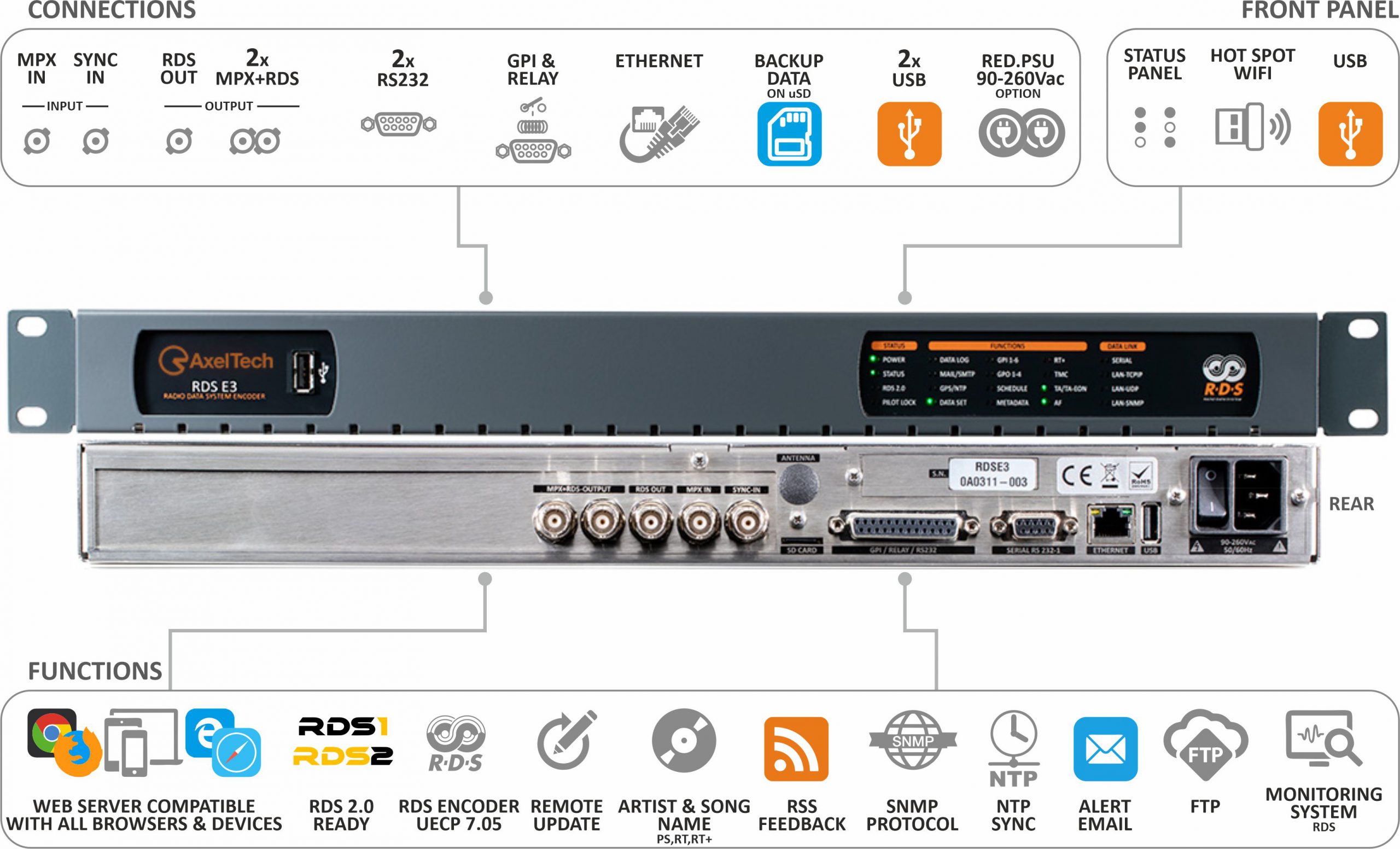
RDS E3-E5
Radio
RDS Encoding and Monitoring
Product Overview
RDS E3 and RDS E5 are static/dynamic RDS Encoders supporting all the services and features requested by an advanced user. RDS E3 and RDS E5 support the most advanced RDS dynamic services, including TMC, ODA, IH, TDC, EWS, Radio Text and Radio Text plus.
In addition to standard CENELEC NRSC methods, RDS programming has been enriched with larger PS and RT sets (that are also available in dynamic mode).
RDS E3 and RDS E5 can interface with various Automation Systems and they offer an ASCII protocol for broadcast song/artist information. In case of alarms, they support SNMP alerting for NMS.
RDS E3 and RDS E5 satisfy the high-end broadcasters’ requirements: UECP system features 4 TCP ports, 4 UDP ports, 2 serial ports and 1 SNMP port.
RDS E3 and RDS E5 are RDS 2.0 Ready: they manage the 4 RDS subcarriers specified in the standard that is still under definition. A web interface has been created to control all these functions and it can be used by any browser with any device from the smartphone to the laptop.
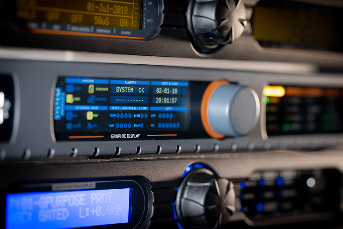
RDS E3 and RDS E5 are SNMP v2c in order to satisfy the most demanding deployments. RDS E3 and RDS E5 have an high resolution colour display that allows the display and insertion of the main machine parameters.
- New features for Dynamic RDS
Models
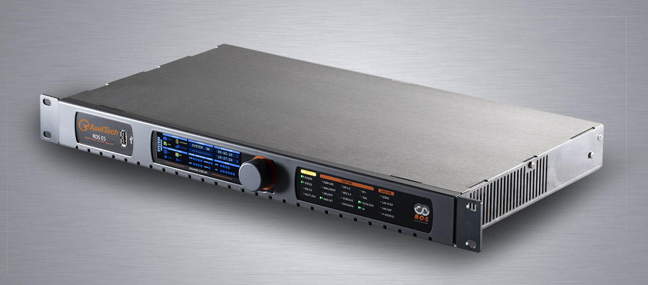
RDS E5

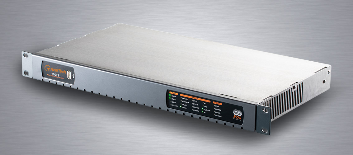
RDS E3
Highlights
General
- Main Supply 90--260Vac 50/60Hz. 15W;
- Green device - only 15W;
- Full Colour Graphic display 480x128 (only RDS RDS E5);
- Status led panel with 40 leds;
- Rack 1u 19” - Inox steel;
- Redundant PSU (available as an option);
- High immunity to strong RF fields, designed to be installed in high power TX sites;
- Fully Digital – No trimmer
Inputs & Outputs Sections
- Double MPX+RDS output with digital level setting;
- RDS output;
- Bypass HW on RDS+MPX Outputs (MPX to Out 1&2);
- 1 MPX input (wide band);
- 1 19kHz Sync imput to synchronize internal RDS.
Encoder RDS Section
- RDS encoder fully compliant with UECP EBU SPB490 v7.05, CENELEC (Europa) and NRSC (America);
- Fully support for all RDS services, Static and Dynamic services;
- UEPC Ports (2 Serials, 4 TCPIP, 4 UDP);
- n.8 Data Set;
- n.10 EON + Main PS for each Data Set;
- Integrated RDS decoder;
- Tuner FM with RDS decoder (as an option);
- Dataset switch managed by UECP/SNMP/REST/HTTP/ASCII PARSER/TXT FILE/GPI;
- Easy to interface to any kind of automation system (UECP/SNMP/REST/HTTP/ASCII PARSER/TXT FILE);
- The RDS can autonomously get data from the Radio Automation System (PS/RT/RT+/TA/MS);
- Easy RDS page fast setup;
- RDS 2.0 Ready.
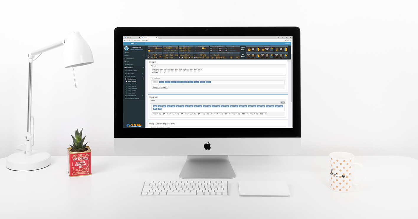
GUI & Monitoring
- Fully programmable by Web GUI interface, all the browsers are supported;
- Simple and intuitive GUI, supported by all devices (PC, notebook, tablet, smartphone, etc.);
- Easy and configurable graphical interface;
- Multi user web GUI;
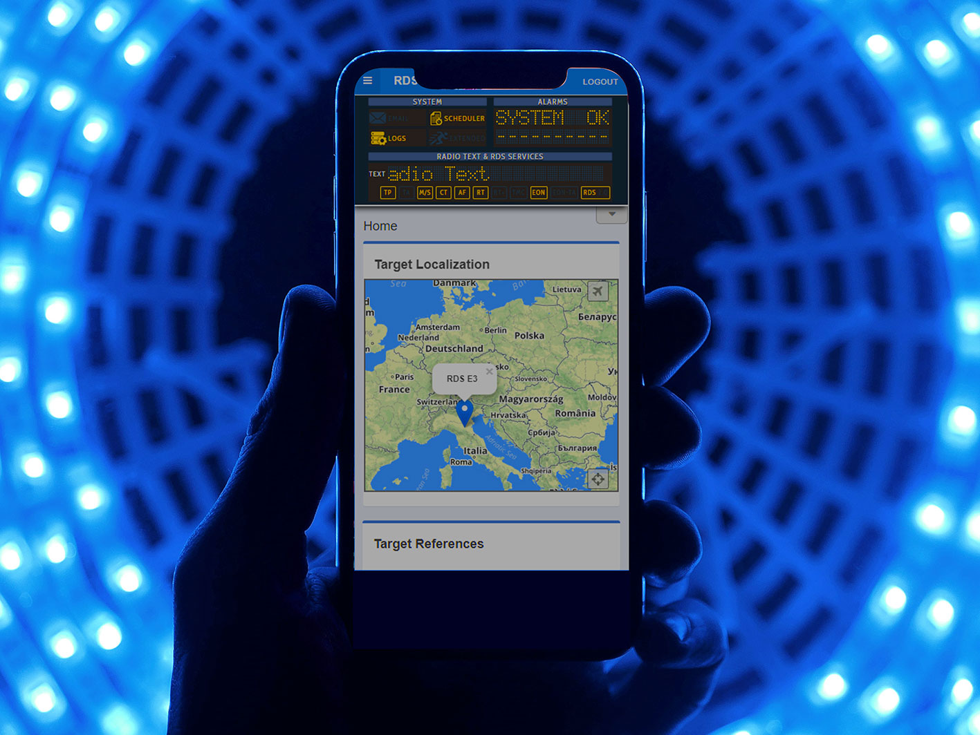
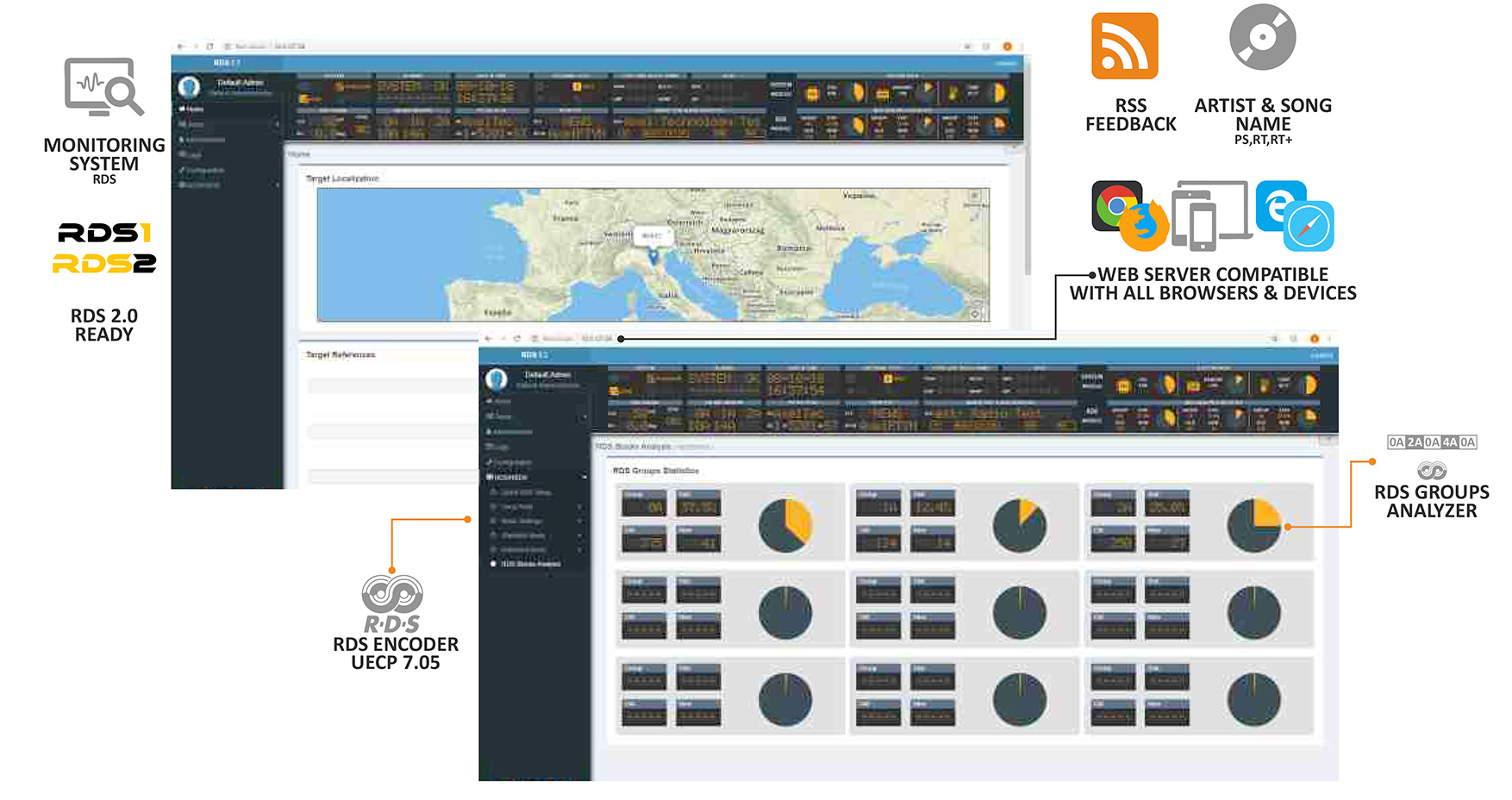
- Map with device geolocation (RX sat or fixed coordinates are required);
- Web GUI with info bubbles;
- Monitoring FM Tuner (as an option);
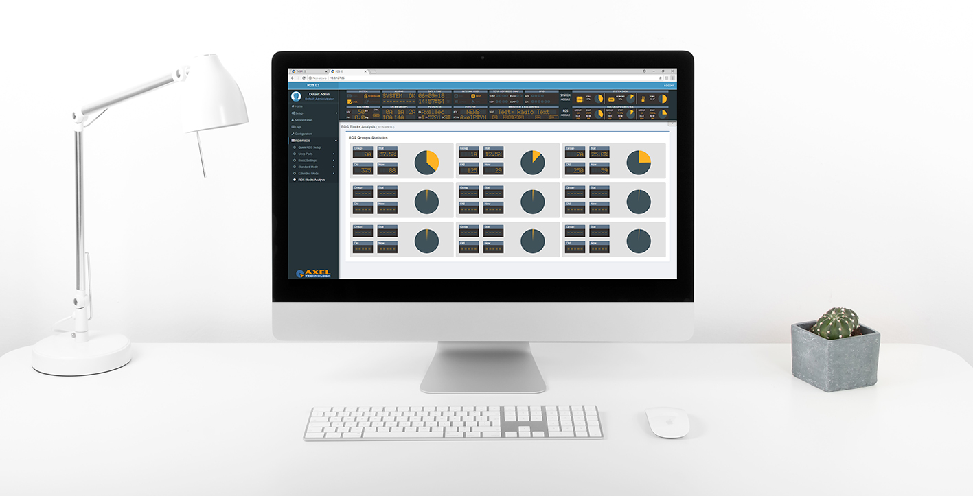
- RDS Groups data analyser;
- GUI with led meter bars.
Communications & Management
- Ethernet/USB/RS232/GPIO connections;
- Easy WiFi Access - Hot spot WiFi USB to connect directly a wireless device to RDS E3 and RDS E5;
- SNMP V2c;
- Possibility to set up to 3 NTP Servers (V1, V2, V3, V4);
- Possibility to send email to 4 receivers and to set 3 different SMPT servers;
- IPV4 and IPV6 support (3 addresses IPV4 and 3 addresses IPV6);
- N°2 RS232 for UECP commands;
- 6 GPI and 4 Relay Out (all GPIO are fully programmable by the GUI);
- HTTP, FTP, SNMP, SMTP, UDP, TCP support;
- Alarms via : TRAP (SNMP), email (SMTP), GPO, HTTP;
- External GPS support (Time, Date and Geolocation);
- uSD Card for clone function, for maintenance and easy replace of a faulty unit;
- Import and export configurations function;
- PRESET, with load/save/import /export functions;
- Logs 24/7 with export function;
- 6 levels of right access managment;
- Easy configuration page setup with info connection diagrams;
- REST API available to manage the device;
- ASCII PARSER interface for easy command line settings;
- SAMBA SHARE function to connect and get data from an external PC;
- Multi-user contemporary access.
Special featuresBroadcast “All” Your Information
RDS E3 and RDS E5 are the result of the long-time AxelTech experience in RDS encoder development.
RDS E3 and RDS E5 can simultaneously receive UECP commands through 4 TCP ports, 4 UDP ports and 2 serial ports, enabling the most demanding network operator to connect all the dynamic sources to the RDS encoder.
In addition to the accurate use of the RDS through UECP commands, RDS E3 and RDS E5 enable the end user to benefit from more simple and flexible ways to send information to the encoder by offering: REST API commands, ASCII Parser and SAMBA connection to Radio Playouts.
RDS E3 and RDS E5 can automatically get information from the Radio Playouts thus eliminating the need of Middleware Software between the Playout and the RDS encoder.
Opened To The Future
RDS E3 and RDS E5 are RDS 2.0 Ready. Their DSP can generate the multicarrier signal needed for the new RDS standard. Once this standard is defined, with a simple software upgrade the end user will be able to have a RDS 2.0 compliant encoder without any replacement that would vanify the initial investement.

Easy Access
RDS E3 and RDS E5 are fully configurable via WEB interface. Their web server is compatible with all the available web browsers (Chrome, Firefox, Edge, Opera, Safari etc.).
RDS E3 and RDS E5 supports laptop, tablet and smartphones simplifying the browsing and setting of the device. They have a responsive-kind graphic interface that adapts the viewing mode according to the resolution and position (portrait/landscape) of the current viewing device.
The provided WiFi USB dongle creates a specific WiFi hotspot that enables the access to the device without the need of cabled or wireless net.
RDS E3 and RDS E5 have 3 IPV4 and 3 IPV6 addresses to ensure simultaneous connection to all the broadcasting and monitoring systems.
Easy Maintenance
Any first-time user can benefit from RDS E3 and RDS E5 simplified settings management.
QUICK RDS SETUP is the easier way to set the main RDS parameters.
IMPORT/EXPORT and PRESET MANAGER are available for RDS E3 and RDS E5’s advanced management.
These functions can be used for the whole device configuration or only for some selectable modules (SYSTEM, RDS, and TUNER).
RDS E3 and RDS E5 use a uSD card to create an automatic copy of all the device data when the user changes anything. If the device needs to be replaced or duplicated, the uSD card can be used to clone it.
Monitoring
RDS E3 and RDS E5 are provided with modern GUI (Graphical User Interface) that uses clear elements and useful information. The wide range of the available banners allows the user to monitor any function. The selected banners are always visible in any menu.
In the RDS section, a specific area is available for on-air RDS group analysis (static and dynamic) to evaluate services balancing.
Thanks to the FM Tuner (as an option), the FM signal can be received and decoded. With this feature it is possible to check MPX, RDS and Pilot deviations, BLER (Block Error Ratio) and RDS Decoder (PI, PS, RT, PTY, RT+,TP, TA, M/S, CT,AF,TMC, EON).
Technical Specifications
MPX Input – MPX
Connector Unbalanced on 2 BNC – EMI Suppressed
Input Impedance 50K
RDS+MPX Output - MPX
Outputs number 3 (2RDS out + 1 RDS)
Connector Unbalanced on 3 BNC – EMI Suppressed
Output Impedance 10 Ω
Load Impedance 600 Ω or greater
Maximum Load Capacitance 5nF
RDS Output Level 0 to 8191 mVpp (1 mVpp step)
S/N > 85dB
Carrier Suppression > 85dB
System
GPIO Inputs/Outputs 6 GPI / 4 GPO
Communication Port 2xRS232, 3xUSB, 1xLAN
Synchronization Ext(Pilot Mpx)/Int/ Auto
Synchronization Monitoring Yes
RDS Level adjustment Digitally controlled
Phase adjustment Yes, 0 ÷ 359.9°
Separate outputs for RDS+MPX and for RDS only Yes
Side Chain Mode, Loop through mode, Bypass feature Yes
RDS Subcarrier 100% Digitally Generated Shape
CENELEC – EN50067 compliant – Yes
Accurate Clock Time (CT) Sync with Internet Connection Yes
Remote TA actuation for Traffic Announcements Yes
GPS module for automatic synchronization of the built-in Real Time Clock (RTC) Optional (USB External)
In-field firmware update Yes
Front-panel Colour TFT Display No (RDS E3) Yes (RDS RDS E5)
Data may be entered on-site with Front-panel knob No (RDS E3) Yes (RDS RDS E5)
Front Panel Leds 40
Operating Temperature 0°C ÷ 50°C
RDS Features
Group supported All
Group Sequence Configurable
PS 8 DSN x MAIN+10 PSN
PI 8 DSN x MAIN+10 PSN
PIN & PTY RDS/RBDS
AF Method A up to 1024 (64 lists)
AF Method B up to 1024 (64 lists)
RT Yes, 32 messages
RT rate adjustment Group Sequence
RT+ for songs and content tagging Yes
TP Yes
TA Control Command, Software, GPI
PTYN Yes
EON 10 PSN
CT Yes
TMC, EWS, IH, TDC Yes
Free Format Groups (FFG) Yes
Open Data Application (ODA) Yes
PS Scrolling Yes
Scrolling by characters, by word, auto centre, long words’ truncation Yes (Characters – from 1 up to 8)
Communication
Connection with Automation Software Yes
Network Connectivity 4 TCP ports / 4 UDP / 1 SNMP
Configuration Software Web Server, FTP
Password Protection Yes
ASCII Protocol Configuration Messages
REST Command Yes
Embedded SNMP agent for active management tasks Yes
Supported Network Protocols HTTP, SMTP, UDP, TCP, NTP, FTP
UECP Protocol EBU SPB490 Ver.7.05
PI Calculator Yes
RDS 2.0 Ready Yes
PSU
Power Supply 90-260 Vac / 47-63 Hz 15W
Dimensions
Dimensions (W; H; D) 485 x 44 x 240 mm
Weight < 3Kg